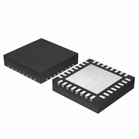
EFM32G200F64 Energy Micro, EFM32G200F64 Datasheet - Page 256

EFM32G200F64
Manufacturer Part Number
EFM32G200F64
Description
MCU 32BIT 64KB FLASH 32-QFN
Manufacturer
Energy Micro
Series
Geckor
Datasheets
1.EFM32G200F16.pdf
(63 pages)
2.EFM32G200F16.pdf
(10 pages)
3.EFM32G200F16.pdf
(463 pages)
4.EFM32G200F16.pdf
(136 pages)
Specifications of EFM32G200F64
Core Processor
ARM® Cortex-M3™
Core Size
32-Bit
Speed
32MHz
Connectivity
EBI/EMI, I²C, IrDA, SmartCard, SPI, UART/USART
Peripherals
Brown-out Detect/Reset, DMA, POR, PWM, WDT
Number Of I /o
24
Program Memory Size
64KB (64K x 8)
Program Memory Type
FLASH
Ram Size
16K x 8
Voltage - Supply (vcc/vdd)
1.8 V ~ 3.8 V
Data Converters
A/D 4x12b, D/A 1x12b
Oscillator Type
External
Operating Temperature
-40°C ~ 85°C
Package / Case
32-VQFN Exposed Pad
Processor Series
EFM32G200
Core
ARM Cortex-M3
Data Bus Width
32 bit
Data Ram Size
16 KB
Interface Type
I2C, UART
Maximum Clock Frequency
32 MHz
Number Of Programmable I/os
24
Number Of Timers
2
Operating Supply Voltage
1.8 V to 3.8 V
Maximum Operating Temperature
+ 85 C
Mounting Style
SMD/SMT
Minimum Operating Temperature
- 40 C
Lead Free Status / RoHS Status
Lead free / RoHS Compliant
Eeprom Size
-
Lead Free Status / Rohs Status
Details
Available stocks
Company
Part Number
Manufacturer
Quantity
Price
- EFM32G200F16 PDF datasheet
- EFM32G200F16 PDF datasheet #2
- EFM32G200F16 PDF datasheet #3
- EFM32G200F16 PDF datasheet #4
- Current page: 256 of 463
- Download datasheet (8Mb)
19.3.3.2 PRS Channel as Source
19.3.3.3 Fault Handling
19.3.3.3.1 Action on Fault
19.3.3.3.2 Exiting Fault State
2010-09-06 - d0001_Rev1.00
A PRS channel can optionally be used as input to the DTI module instead of the PWM output from the
timer. Setting DTPRSEN in TIMER0_DTCTRL will override the source of the first DTI channel, driving
TIM0_CC0 and TIM0_CDTI0, with the value on the PRS channel. The rest of the DTI channels will
continue to be driven by the PWM output from the timer. The PRS channel to use is chosen by configuring
DTPRSSEL in TIMER0_DTCTRL. Note that the timer must be running even when PRS is used as DTI
source.
The DTI prescaler, set by DTPRESC in TIMER0_DTTIMEdetermines with which accuracy the DTI can
insert dead-time into a PRS signal. The maximum dead-time error equals 2
zero prescaling, the inserted dead-times are therefore accurate, but they may be inaccurate for larger
prescaler settings.
The fault handling system of the DTI unit allows the outputs of the DTI unit to be put in a well-defined
state in case of a fault. This hardware fault handling system makes a fast reaction to faults possible,
reducing the possibility of damage to the system.
The fault sources which trigger a fault in the DTI module are determined by TIMER0_DTFSEN. Any
combination of the available error sources can be selected:
• PRS source 0, determined by DTPRS0FSEL in TIMER0_DTFC
• PRS source 1, determined by DTPRS1FSEL in TIMER0_DTFC
• Debugger
• Core Lockup
One or two PRS channels can be used as an error source. When PRS source 0 is selected as an error
source, DTPRS0FSEL determines which PRS channel is used for this source. DTPRS1FSEL determines
which PRS channel is selected as PRS source 1. Please note that for Core Lockup, the LOCKUPRDIS
in RMU_CTRL must be set. Otherwise this will generate a full reset of the EFM32.
When a fault occurs, the bit representing the fault source is set in DTFS, and the outputs from the DTI unit
are set to a well-defined state. The following options are available, and can be enabled by configuring
DTFACT in TIMER0_DTFC:
• Set outputs to inactive level
• Clear outputs
• Tristate outputs
With the first option enabled, the output state in case of a fault depends on the polarity settings for the
individual outputs. An output set to be active high will be set low if a fault is detected, while an output
set to be active low will be driven high.
When a fault occurs, the fault source(s) can be read out of TIMER0_DTFS. TIMER0_DTFS is organized
in the same way as DTFSEN, with one bit for each source.
When a fault is triggered by the PRS system, software intervention is required to re-enable the outputs
of the DTI unit. This is done by manually clearing TIMER0_DTFS. If the fault cause, determined by
TIMER0_DTFS, is the debugger alone, the outputs can optionally be re-enabled when the debugger
exits and the processor resumes normal operation. The corresponding bit in TIMER0_DTFS will in that
case be cleared by hardware. The automatic startup functionality can be enabled by setting DTDAS in
...the world's most energy friendly microcontrollers
256
DTPRESC
www.energymicro.com
clock cycles. With
Related parts for EFM32G200F64
Image
Part Number
Description
Manufacturer
Datasheet
Request
R

Part Number:
Description:
KIT STARTER EFM32 GECKO
Manufacturer:
Energy Micro
Datasheet:

Part Number:
Description:
KIT DEV EFM32 GECKO LCD SUPPORT
Manufacturer:
Energy Micro
Datasheet:

Part Number:
Description:
BOARD PROTOTYPING FOR EFM32
Manufacturer:
Energy Micro
Datasheet:

Part Number:
Description:
KIT DEVELOPMENT EFM32 GECKO
Manufacturer:
Energy Micro
Datasheet:

Part Number:
Description:
MCU, MPU & DSP Development Tools TG840 Sample Kit
Manufacturer:
Energy Micro
Datasheet:

Part Number:
Description:
MCU, MPU & DSP Development Tools TG Starter Kit
Manufacturer:
Energy Micro
Datasheet:

Part Number:
Description:
MCU, MPU & DSP Development Tools TG108 Sample Kit
Manufacturer:
Energy Micro

Part Number:
Description:
MCU, MPU & DSP Development Tools TG210 Sample Kit
Manufacturer:
Energy Micro
Datasheet:

Part Number:
Description:
MCU, MPU & DSP Development Tools TG822 Sample Kit
Manufacturer:
Energy Micro
Datasheet:

Part Number:
Description:
MCU, MPU & DSP Development Tools TG230 Sample Kit
Manufacturer:
Energy Micro

Part Number:
Description:
SAMPLE KIT (SMALL BOX - CONTAINING 2 DEVICES)
Manufacturer:
Energy Micro

Part Number:
Description:
SAMPLE KIT (SMALL BOX - CONTAINING 2 DEVICES)
Manufacturer:
Energy Micro


