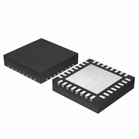
EFM32G200F64 Energy Micro, EFM32G200F64 Datasheet - Page 149

EFM32G200F64
Manufacturer Part Number
EFM32G200F64
Description
MCU 32BIT 64KB FLASH 32-QFN
Manufacturer
Energy Micro
Series
Geckor
Datasheets
1.EFM32G200F16.pdf
(63 pages)
2.EFM32G200F16.pdf
(10 pages)
3.EFM32G200F16.pdf
(463 pages)
4.EFM32G200F16.pdf
(136 pages)
Specifications of EFM32G200F64
Core Processor
ARM® Cortex-M3™
Core Size
32-Bit
Speed
32MHz
Connectivity
EBI/EMI, I²C, IrDA, SmartCard, SPI, UART/USART
Peripherals
Brown-out Detect/Reset, DMA, POR, PWM, WDT
Number Of I /o
24
Program Memory Size
64KB (64K x 8)
Program Memory Type
FLASH
Ram Size
16K x 8
Voltage - Supply (vcc/vdd)
1.8 V ~ 3.8 V
Data Converters
A/D 4x12b, D/A 1x12b
Oscillator Type
External
Operating Temperature
-40°C ~ 85°C
Package / Case
32-VQFN Exposed Pad
Processor Series
EFM32G200
Core
ARM Cortex-M3
Data Bus Width
32 bit
Data Ram Size
16 KB
Interface Type
I2C, UART
Maximum Clock Frequency
32 MHz
Number Of Programmable I/os
24
Number Of Timers
2
Operating Supply Voltage
1.8 V to 3.8 V
Maximum Operating Temperature
+ 85 C
Mounting Style
SMD/SMT
Minimum Operating Temperature
- 40 C
Lead Free Status / RoHS Status
Lead free / RoHS Compliant
Eeprom Size
-
Lead Free Status / Rohs Status
Details
Available stocks
Company
Part Number
Manufacturer
Quantity
Price
- EFM32G200F16 PDF datasheet
- EFM32G200F16 PDF datasheet #2
- EFM32G200F16 PDF datasheet #3
- EFM32G200F16 PDF datasheet #4
- Current page: 149 of 463
- Download datasheet (8Mb)
15.3.7.1 Master State Machine
2010-09-06 - d0001_Rev1.00
After the address has been transmitted, a sequence of bytes can be read from or written to the slave,
depending on the value of the R/W bit (bit 0 in the address byte). If the bit was cleared, the master
has entered a master transmitter role, where it now transmits data to the slave. If the bit was set, it
has entered a master receiver role, where it now should receive data from the slave. In either case, an
unlimited number of bytes can be transferred in one direction during the transmission.
At the end of the transmission, the master either transmits a repeated START condition (Sr) if it wishes
to continue with another transfer, or transmits a STOP condition (P) if it wishes to release the bus.
The master state machine is shown in Figure 15.10 (p. 149) . A master operation starts in the far
left of the state machine, and follows the solid lines through the state machine, ending the operation or
continuing with a new operation when arriving at the right side of the state machine.
Branches in the path through the state machine are the results of bus events and choices made by
software, either directly or indirectly. The dotted lines show where I
along the path and the full-drawn circles show places where interaction may be required by software
to let the transmission proceed.
Figure 15.10. I
0/1
Sr
ADDR W
ADDR R
S
A
Received from slave
Transm itted by self
Bus state/event
START
condition
Repeated START condition
ACK
Interaction required. Wait-
states inserted until m anual
or autom atic interaction has
been perform ed
Idle/busy
Interrupt flag set
Slave address + write
(R/W bit cleared)
Slave address + read
(R/W bit set)
2
C Master State Machine
Bus state (STATE)
Waiting
N
P
for idle
Go to state
STOP
condition
NACK
S
57
ADDR W
ADDR R
ADDR R
ADDR W
ADDR X
P
Master transm itter
Master receiver
Arbitration lost
Bus reset
...the world's most energy friendly microcontrollers
149
Arb. lost, ADDR m atch
Arb. lost, ADDR m atch
Arb. lost, no m atch
A
N
A
N
9F
9B
97
93
DATA
DATA
2
C-specific interrupt flags are set
B3
A
N
Arb. lost
73
71
1
0
N
A
DF
D7
www.energymicro.com
X
Slave transm itter
Slave receiver
Arb. lost
Sr
Sr
P
P
57
57
0
1
0
1
Related parts for EFM32G200F64
Image
Part Number
Description
Manufacturer
Datasheet
Request
R

Part Number:
Description:
KIT STARTER EFM32 GECKO
Manufacturer:
Energy Micro
Datasheet:

Part Number:
Description:
KIT DEV EFM32 GECKO LCD SUPPORT
Manufacturer:
Energy Micro
Datasheet:

Part Number:
Description:
BOARD PROTOTYPING FOR EFM32
Manufacturer:
Energy Micro
Datasheet:

Part Number:
Description:
KIT DEVELOPMENT EFM32 GECKO
Manufacturer:
Energy Micro
Datasheet:

Part Number:
Description:
MCU, MPU & DSP Development Tools TG840 Sample Kit
Manufacturer:
Energy Micro
Datasheet:

Part Number:
Description:
MCU, MPU & DSP Development Tools TG Starter Kit
Manufacturer:
Energy Micro
Datasheet:

Part Number:
Description:
MCU, MPU & DSP Development Tools TG108 Sample Kit
Manufacturer:
Energy Micro

Part Number:
Description:
MCU, MPU & DSP Development Tools TG210 Sample Kit
Manufacturer:
Energy Micro
Datasheet:

Part Number:
Description:
MCU, MPU & DSP Development Tools TG822 Sample Kit
Manufacturer:
Energy Micro
Datasheet:

Part Number:
Description:
MCU, MPU & DSP Development Tools TG230 Sample Kit
Manufacturer:
Energy Micro

Part Number:
Description:
SAMPLE KIT (SMALL BOX - CONTAINING 2 DEVICES)
Manufacturer:
Energy Micro

Part Number:
Description:
SAMPLE KIT (SMALL BOX - CONTAINING 2 DEVICES)
Manufacturer:
Energy Micro


