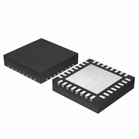
EFM32G200F64 Energy Micro, EFM32G200F64 Datasheet - Page 51

EFM32G200F64
Manufacturer Part Number
EFM32G200F64
Description
MCU 32BIT 64KB FLASH 32-QFN
Manufacturer
Energy Micro
Series
Geckor
Datasheets
1.EFM32G200F16.pdf
(63 pages)
2.EFM32G200F16.pdf
(10 pages)
3.EFM32G200F16.pdf
(463 pages)
4.EFM32G200F16.pdf
(136 pages)
Specifications of EFM32G200F64
Core Processor
ARM® Cortex-M3™
Core Size
32-Bit
Speed
32MHz
Connectivity
EBI/EMI, I²C, IrDA, SmartCard, SPI, UART/USART
Peripherals
Brown-out Detect/Reset, DMA, POR, PWM, WDT
Number Of I /o
24
Program Memory Size
64KB (64K x 8)
Program Memory Type
FLASH
Ram Size
16K x 8
Voltage - Supply (vcc/vdd)
1.8 V ~ 3.8 V
Data Converters
A/D 4x12b, D/A 1x12b
Oscillator Type
External
Operating Temperature
-40°C ~ 85°C
Package / Case
32-VQFN Exposed Pad
Processor Series
EFM32G200
Core
ARM Cortex-M3
Data Bus Width
32 bit
Data Ram Size
16 KB
Interface Type
I2C, UART
Maximum Clock Frequency
32 MHz
Number Of Programmable I/os
24
Number Of Timers
2
Operating Supply Voltage
1.8 V to 3.8 V
Maximum Operating Temperature
+ 85 C
Mounting Style
SMD/SMT
Minimum Operating Temperature
- 40 C
Lead Free Status / RoHS Status
Lead free / RoHS Compliant
Eeprom Size
-
Lead Free Status / Rohs Status
Details
Available stocks
Company
Part Number
Manufacturer
Quantity
Price
- EFM32G200F16 PDF datasheet
- EFM32G200F16 PDF datasheet #2
- EFM32G200F16 PDF datasheet #3
- EFM32G200F16 PDF datasheet #4
- Current page: 51 of 463
- Download datasheet (8Mb)
2010-09-06 - d0001_Rev1.00
• provide a contiguous area of system memory that the controller and host processor can access
• have a base address that is an integer multiple of the total size of the channel control data structure.
Figure 8.6 (p. 51) shows the memory that the controller requires for the channel control data structure,
when all 8 channels and the optional alternate data structure are in use.
Figure 8.6. Memory map for 8 channels, including the alternate data structure
This structure in Figure 8.6 (p. 51) uses 256 bytes of system memory. The controller uses the lower
8 address bits to enable it to access all of the elements in the structure and therefore the base address
must be at 0xXXXXXX00.
You can configure the base address for the primary data structure by writing the appropriate value in
the DMA_CTRLBASE register.
You do not need to set aside the full 256 bytes if not all 8 channels are used or not all alternate descriptors
are used. If e.g. only 4 channels are used and they only need the primary descriptors, then only 64 bytes
need be set aside.
Table 8.6 (p. 51) lists the address bits that the controller uses when it accesses the elements of the
channel control data structure.
Table 8.6. Address bit settings for the channel control data structure
Where:
A
C[2:0]
Address[3:0]
Note
Figure 8.7 (p. 52) shows a detailed memory map of the descriptor structure.
Address bits
[7]
A
Alternate data structure
Alternate_Ch_7
Alternate_Ch_6
Alternate_Ch_5
Alternate_Ch_4
Alternate_Ch_3
Alternate_Ch_2
Alternate_Ch_1
Alternate_Ch_0
It is not necessary for you to calculate the base address of the alternate data structure
because the DMA_ALTCTRLBASE register provides this information.
0x0D0
0x0C0
0x100
0x0F0
0x0E0
0x0B0
0x0A0
0x090
0x080
Selects one of the channel control data structures:
A = 0
A = 1
Selects the DMA channel.
Selects one of the control elements:
0x0 Selects the source data end pointer.
0x4 Selects the destination data end pointer.
0x8 Selects the control data configuration.
0xC The controller does not access this address location. If required, you can
[6]
C[2]
enable the host processor to use this memory location as system memory.
Prim ary data structure
Prim ary_Ch_7
Prim ary_Ch_6
Prim ary_Ch_5
Prim ary_Ch_4
Prim ary_Ch_3
Prim ary_Ch_2
Prim ary_Ch_1
Prim ary_Ch_0
Selects the primary data structure.
Selects the alternate data structure.
0x080
0x070
0x060
0x050
0x040
0x030
0x020
0x010
0x000
[5]
C[1]
...the world's most energy friendly microcontrollers
51
Destination End Pointer
Source End Pointer
Unused
Control
[4]
C[0]
0x00C
0x008
0x004
0x000
www.energymicro.com
[3:0]
0x0, 0x4, or 0x8
Related parts for EFM32G200F64
Image
Part Number
Description
Manufacturer
Datasheet
Request
R

Part Number:
Description:
KIT STARTER EFM32 GECKO
Manufacturer:
Energy Micro
Datasheet:

Part Number:
Description:
KIT DEV EFM32 GECKO LCD SUPPORT
Manufacturer:
Energy Micro
Datasheet:

Part Number:
Description:
BOARD PROTOTYPING FOR EFM32
Manufacturer:
Energy Micro
Datasheet:

Part Number:
Description:
KIT DEVELOPMENT EFM32 GECKO
Manufacturer:
Energy Micro
Datasheet:

Part Number:
Description:
MCU, MPU & DSP Development Tools TG840 Sample Kit
Manufacturer:
Energy Micro
Datasheet:

Part Number:
Description:
MCU, MPU & DSP Development Tools TG Starter Kit
Manufacturer:
Energy Micro
Datasheet:

Part Number:
Description:
MCU, MPU & DSP Development Tools TG108 Sample Kit
Manufacturer:
Energy Micro

Part Number:
Description:
MCU, MPU & DSP Development Tools TG210 Sample Kit
Manufacturer:
Energy Micro
Datasheet:

Part Number:
Description:
MCU, MPU & DSP Development Tools TG822 Sample Kit
Manufacturer:
Energy Micro
Datasheet:

Part Number:
Description:
MCU, MPU & DSP Development Tools TG230 Sample Kit
Manufacturer:
Energy Micro

Part Number:
Description:
SAMPLE KIT (SMALL BOX - CONTAINING 2 DEVICES)
Manufacturer:
Energy Micro

Part Number:
Description:
SAMPLE KIT (SMALL BOX - CONTAINING 2 DEVICES)
Manufacturer:
Energy Micro


