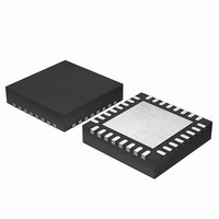
EFM32G200F64 Energy Micro, EFM32G200F64 Datasheet - Page 144

EFM32G200F64
Manufacturer Part Number
EFM32G200F64
Description
MCU 32BIT 64KB FLASH 32-QFN
Manufacturer
Energy Micro
Series
Geckor
Datasheets
1.EFM32G200F16.pdf
(63 pages)
2.EFM32G200F16.pdf
(10 pages)
3.EFM32G200F16.pdf
(463 pages)
4.EFM32G200F16.pdf
(136 pages)
Specifications of EFM32G200F64
Core Processor
ARM® Cortex-M3™
Core Size
32-Bit
Speed
32MHz
Connectivity
EBI/EMI, I²C, IrDA, SmartCard, SPI, UART/USART
Peripherals
Brown-out Detect/Reset, DMA, POR, PWM, WDT
Number Of I /o
24
Program Memory Size
64KB (64K x 8)
Program Memory Type
FLASH
Ram Size
16K x 8
Voltage - Supply (vcc/vdd)
1.8 V ~ 3.8 V
Data Converters
A/D 4x12b, D/A 1x12b
Oscillator Type
External
Operating Temperature
-40°C ~ 85°C
Package / Case
32-VQFN Exposed Pad
Processor Series
EFM32G200
Core
ARM Cortex-M3
Data Bus Width
32 bit
Data Ram Size
16 KB
Interface Type
I2C, UART
Maximum Clock Frequency
32 MHz
Number Of Programmable I/os
24
Number Of Timers
2
Operating Supply Voltage
1.8 V to 3.8 V
Maximum Operating Temperature
+ 85 C
Mounting Style
SMD/SMT
Minimum Operating Temperature
- 40 C
Lead Free Status / RoHS Status
Lead free / RoHS Compliant
Eeprom Size
-
Lead Free Status / Rohs Status
Details
Available stocks
Company
Part Number
Manufacturer
Quantity
Price
- EFM32G200F16 PDF datasheet
- EFM32G200F16 PDF datasheet #2
- EFM32G200F16 PDF datasheet #3
- EFM32G200F16 PDF datasheet #4
- Current page: 144 of 463
- Download datasheet (8Mb)
15.3.1.1 START and STOP Conditions
15.3.1.2 Bus Transfer
2010-09-06 - d0001_Rev1.00
START and STOP conditions are used to initiate and stop transactions on the I
the bus begin with a START condition (S) and end with a STOP condition (P). As shown in Figure 15.3 (p.
144) , a START condition is generated by pulling the SDA line low while SCL is high, and a STOP
condition is generated by pulling the SDA line high while SCL is high.
Figure 15.3. I
The START and STOP conditions are easily identifiable bus events as they are the only conditions on
the bus where a transition is allowed on SDA while SCL is high. During the actual data transmission, SDA
is only allowed to change while SCL is low, and must be stable while SCL is high. One bit is transferred
per clock pulse on the I
Figure 15.4. I
When a master wants to initiate a transfer on the bus, it waits until the bus is idle and transmits a START
condition on the bus. The master then transmits the address of the slave it wishes to interact with and
a single R/W bit telling whether it wishes to read from the slave (R/W bit set to 1) or write to the slave
(R/W bit set to 0).
After the 7-bit address and the R/W bit, the master releases the bus, allowing the slave to acknowledge
the request. During the next bit-period, the slave pulls SDA low (ACK) if it acknowledges the request,
or keeps it high if it does not acknowledge it (NACK).
Following the address acknowledge, either the slave or master transmits data, depending on the value
of the R/W bit. After every 8-bit byte transmitted on the SDA line, the transmitter releases the line to
allow the receiver to transmit an ACK or a NACK. Both the data and the address are transmitted with
the most significant bit first.
The number of bytes in a bus transfer is unrestricted. The master ends the transmission after a (N)ACK
by sending a STOP condition on the bus. After a STOP condition, any master wishing to initiate a transfer
on the bus can try to gain control of it. If the current master wishes to make another transfer immediately
after the current, it can start a new transfer directly by transmitting a repeated START condition (Sr)
instead of a STOP followed by a START.
The GPIO drive strength can be used to control slew rate.
2
2
C START and STOP Conditions
C Bit Transfer on I
SDA
SCL
START condition
2
C-bus as shown in Figure 15.2 (p. 143) .
S
SDA
SCL
2
C-Bus
Data change
allowed
...the world's most energy friendly microcontrollers
Data stable
144
Data change
allowed
STOP condition
2
C-bus. All transactions on
www.energymicro.com
P
Related parts for EFM32G200F64
Image
Part Number
Description
Manufacturer
Datasheet
Request
R

Part Number:
Description:
KIT STARTER EFM32 GECKO
Manufacturer:
Energy Micro
Datasheet:

Part Number:
Description:
KIT DEV EFM32 GECKO LCD SUPPORT
Manufacturer:
Energy Micro
Datasheet:

Part Number:
Description:
BOARD PROTOTYPING FOR EFM32
Manufacturer:
Energy Micro
Datasheet:

Part Number:
Description:
KIT DEVELOPMENT EFM32 GECKO
Manufacturer:
Energy Micro
Datasheet:

Part Number:
Description:
MCU, MPU & DSP Development Tools TG840 Sample Kit
Manufacturer:
Energy Micro
Datasheet:

Part Number:
Description:
MCU, MPU & DSP Development Tools TG Starter Kit
Manufacturer:
Energy Micro
Datasheet:

Part Number:
Description:
MCU, MPU & DSP Development Tools TG108 Sample Kit
Manufacturer:
Energy Micro

Part Number:
Description:
MCU, MPU & DSP Development Tools TG210 Sample Kit
Manufacturer:
Energy Micro
Datasheet:

Part Number:
Description:
MCU, MPU & DSP Development Tools TG822 Sample Kit
Manufacturer:
Energy Micro
Datasheet:

Part Number:
Description:
MCU, MPU & DSP Development Tools TG230 Sample Kit
Manufacturer:
Energy Micro

Part Number:
Description:
SAMPLE KIT (SMALL BOX - CONTAINING 2 DEVICES)
Manufacturer:
Energy Micro

Part Number:
Description:
SAMPLE KIT (SMALL BOX - CONTAINING 2 DEVICES)
Manufacturer:
Energy Micro


