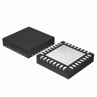
EFM32G200F64 Energy Micro, EFM32G200F64 Datasheet - Page 348

EFM32G200F64
Manufacturer Part Number
EFM32G200F64
Description
MCU 32BIT 64KB FLASH 32-QFN
Manufacturer
Energy Micro
Series
Geckor
Datasheets
1.EFM32G200F16.pdf
(63 pages)
2.EFM32G200F16.pdf
(10 pages)
3.EFM32G200F16.pdf
(463 pages)
4.EFM32G200F16.pdf
(136 pages)
Specifications of EFM32G200F64
Core Processor
ARM® Cortex-M3™
Core Size
32-Bit
Speed
32MHz
Connectivity
EBI/EMI, I²C, IrDA, SmartCard, SPI, UART/USART
Peripherals
Brown-out Detect/Reset, DMA, POR, PWM, WDT
Number Of I /o
24
Program Memory Size
64KB (64K x 8)
Program Memory Type
FLASH
Ram Size
16K x 8
Voltage - Supply (vcc/vdd)
1.8 V ~ 3.8 V
Data Converters
A/D 4x12b, D/A 1x12b
Oscillator Type
External
Operating Temperature
-40°C ~ 85°C
Package / Case
32-VQFN Exposed Pad
Processor Series
EFM32G200
Core
ARM Cortex-M3
Data Bus Width
32 bit
Data Ram Size
16 KB
Interface Type
I2C, UART
Maximum Clock Frequency
32 MHz
Number Of Programmable I/os
24
Number Of Timers
2
Operating Supply Voltage
1.8 V to 3.8 V
Maximum Operating Temperature
+ 85 C
Mounting Style
SMD/SMT
Minimum Operating Temperature
- 40 C
Lead Free Status / RoHS Status
Lead free / RoHS Compliant
Eeprom Size
-
Lead Free Status / Rohs Status
Details
Available stocks
Company
Part Number
Manufacturer
Quantity
Price
- EFM32G200F16 PDF datasheet
- EFM32G200F16 PDF datasheet #2
- EFM32G200F16 PDF datasheet #3
- EFM32G200F16 PDF datasheet #4
- Current page: 348 of 463
- Download datasheet (8Mb)
25.3.10.1 Offset Calibration
25.3.10.2 Gain Calibration
2010-09-06 - d0001_Rev1.00
The effects of changing the calibration register values are given in Table 25.5 (p. 348) . Step
by step calibration procedures for offset and gain are given in Section 25.3.10.1 (p. 348) and
Section 25.3.10.2 (p. 348) .
Table 25.5. Calibration Register Effect
The offset calibration register expects a signed 2’s complement value with negative effect. A high value
gives a low ADC reading.
The gain calibration register expects an unsigned value with positive effect. A high value gives a high
ADC reading.
Offset calibration must be performed prior to gain calibration. Follow these steps for the offset calibration
in single mode:
1. Select wanted reference by setting the REF bitfield of the ADCn_SINGLECTRL register.
2. Set the AT bitfield of the ADCn_SINGLECTRL register to 16CYCLES.
3. Set the INPUTSEL bitfield of the ADCn_SINGLECTRL register to DIFF0, and set the DIFF bitfield to
4. A binary search is used to find the offset calibration value. Set the SINGLESTART bit in the
Offset calibration must be performed prior to gain calibration. The Gain Calibration is done in the following
manner:
1. Select an external ADC channel (a differential channel can also be used).
2. Apply an external voltage on the selected ADC input channel. This voltage should correspond to the
3. A binary search is used to find the gain calibration value. Set the SINGLESTART bit in the
1 for enabling differential input. Since the input voltage is 0, the expected ADC output is the half of
the ADC code range as it is in differential mode.
ADCn_CTRL register and read the ADCn_SINGLEDATA register. The result of the binary search is
written to the SINGLEOFFSET field of the ADCn_CAL register.
top of the ADC range.
ADCn_CTRL register and read the ADCn_SINGLEDATA register. The target value is ideally the top
of the ADC range, but it is recommended to use a value a couple of LSBs below in order to avoid
overshooting. The result of the binary search is written to the SINGLEGAIN field of the ADCn_CAL
register.
Calibration Register
Offset
Gain
Lowest Output
Highest Output
Lowest Output
Highest Output
ADC Result
...the world's most energy friendly microcontrollers
348
0111111
1000000
0000000
1111111
Calibration Binary Value
3F
40
00
7F
www.energymicro.com
Calibration Hex Value
Related parts for EFM32G200F64
Image
Part Number
Description
Manufacturer
Datasheet
Request
R

Part Number:
Description:
KIT STARTER EFM32 GECKO
Manufacturer:
Energy Micro
Datasheet:

Part Number:
Description:
KIT DEV EFM32 GECKO LCD SUPPORT
Manufacturer:
Energy Micro
Datasheet:

Part Number:
Description:
BOARD PROTOTYPING FOR EFM32
Manufacturer:
Energy Micro
Datasheet:

Part Number:
Description:
KIT DEVELOPMENT EFM32 GECKO
Manufacturer:
Energy Micro
Datasheet:

Part Number:
Description:
MCU, MPU & DSP Development Tools TG840 Sample Kit
Manufacturer:
Energy Micro
Datasheet:

Part Number:
Description:
MCU, MPU & DSP Development Tools TG Starter Kit
Manufacturer:
Energy Micro
Datasheet:

Part Number:
Description:
MCU, MPU & DSP Development Tools TG108 Sample Kit
Manufacturer:
Energy Micro

Part Number:
Description:
MCU, MPU & DSP Development Tools TG210 Sample Kit
Manufacturer:
Energy Micro
Datasheet:

Part Number:
Description:
MCU, MPU & DSP Development Tools TG822 Sample Kit
Manufacturer:
Energy Micro
Datasheet:

Part Number:
Description:
MCU, MPU & DSP Development Tools TG230 Sample Kit
Manufacturer:
Energy Micro

Part Number:
Description:
SAMPLE KIT (SMALL BOX - CONTAINING 2 DEVICES)
Manufacturer:
Energy Micro

Part Number:
Description:
SAMPLE KIT (SMALL BOX - CONTAINING 2 DEVICES)
Manufacturer:
Energy Micro


