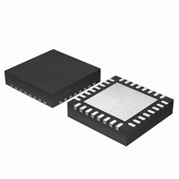
EFM32G200F64 Energy Micro, EFM32G200F64 Datasheet - Page 295

EFM32G200F64
Manufacturer Part Number
EFM32G200F64
Description
MCU 32BIT 64KB FLASH 32-QFN
Manufacturer
Energy Micro
Series
Geckor
Datasheets
1.EFM32G200F16.pdf
(63 pages)
2.EFM32G200F16.pdf
(10 pages)
3.EFM32G200F16.pdf
(463 pages)
4.EFM32G200F16.pdf
(136 pages)
Specifications of EFM32G200F64
Core Processor
ARM® Cortex-M3™
Core Size
32-Bit
Speed
32MHz
Connectivity
EBI/EMI, I²C, IrDA, SmartCard, SPI, UART/USART
Peripherals
Brown-out Detect/Reset, DMA, POR, PWM, WDT
Number Of I /o
24
Program Memory Size
64KB (64K x 8)
Program Memory Type
FLASH
Ram Size
16K x 8
Voltage - Supply (vcc/vdd)
1.8 V ~ 3.8 V
Data Converters
A/D 4x12b, D/A 1x12b
Oscillator Type
External
Operating Temperature
-40°C ~ 85°C
Package / Case
32-VQFN Exposed Pad
Processor Series
EFM32G200
Core
ARM Cortex-M3
Data Bus Width
32 bit
Data Ram Size
16 KB
Interface Type
I2C, UART
Maximum Clock Frequency
32 MHz
Number Of Programmable I/os
24
Number Of Timers
2
Operating Supply Voltage
1.8 V to 3.8 V
Maximum Operating Temperature
+ 85 C
Mounting Style
SMD/SMT
Minimum Operating Temperature
- 40 C
Lead Free Status / RoHS Status
Lead free / RoHS Compliant
Eeprom Size
-
Lead Free Status / Rohs Status
Details
Available stocks
Company
Part Number
Manufacturer
Quantity
Price
- EFM32G200F16 PDF datasheet
- EFM32G200F16 PDF datasheet #2
- EFM32G200F16 PDF datasheet #3
- EFM32G200F16 PDF datasheet #4
- Current page: 295 of 463
- Download datasheet (8Mb)
21.3.5.2 Continuous Output Generation
2010-09-06 - d0001_Rev1.00
Example 21.2. LETIMER Continuous Output Generation
In some scenarios, it might be desired to make LETIMER generate a continuous waveform. Very simple
constant waveforms can be generated without the repeat counter as shown in Figure 21.6 (p. 293) , but
to generate changing waveforms, using the repeat counter and buffer registers can prove advantageous.
For the example in Figure 21.10 (p. 295) , the goal is to produce a pulse train consisting of 3 sequences
with the following properties:
• 3 pulses with periods of 3 cycles
• 4 pulses with periods of 2 cycles
• 2 pulses with periods of 3 cycles
Figure 21.10. LETIMER Continuous Operation
The first two sequences are loaded into the LETIMER before the timer is started.
LETIMERn_COMP0 is set to 2 (cycles – 1), and LETIMERn_REP0 is set to 3 for the first sequence, and
the second sequence is loaded into the buffer registers, i.e. COMP1 is set to 1 and LETIMERn_REP1
is set to 4.
The LETIMER is set to trigger an interrupt when LETIMERn_REP0 is done by setting REP0 in
LETIMERn_IEN. This interrupt is a good place to update the values of the buffers. Last but not least
REPMODE in LETIMERn_CTRL is set to buffered mode, and the timer is started.
In the interrupt routine the buffers are updated with the values for the third sequence. If this had not been
done, the timer would have stopped after the second sequence.
The final result is shown in Figure 21.10 (p. 295) . The pulse output is grouped to show which sequence
generated which output. Toggle output is also shown in the figure. Note that the toggle output is not
aligned with the pulse outputs.
Note
LFACLK
UFOA0 = 01
UFOA0 = 10
Int. flags set
LETn_O0
LETn_O1
COMP1
COMP0
LETIMERn
REP0
REP1
Initial configuration,
CNT
REPB just written
1
2
0
3
4
1
2
2
3
4
1
2
1
3
4
UFIF
1
2
0
3
4
1
2
2
2
4
Pulse Seq. 1
1
2
1
2
4
UFIF
1
2
0
2
4
1
2
2
1
4
4
1
2
1
1
REP0IF
UFIF
1
2
0
1
4
4
1
1
1
4
...the world's most energy friendly microcontrollers
u
295
4
1
1
0
4
COMP1 = 2
u
REP1 = 2
4
1
1
1
3
Write
u
UFIF
2
1
0
3
2
Pulse Seq. 2
2
1
1
2
2
UFIF
2
1
0
2
2
2
1
1
1
2
REP0IF
UFIF
2
1
0
1
2 2
2
2
2
2
u
2
2
2
1
2
u
2
2
2
0
2
Pulse Seq. 3
u
UFIF
www.energymicro.com
2
2
2
2
1
u
2
2
2
1
1
REP0IF
final values
u
UFIF
2
Stop,
2
2
0
1
u
2
2
2
0
0
u
Related parts for EFM32G200F64
Image
Part Number
Description
Manufacturer
Datasheet
Request
R

Part Number:
Description:
KIT STARTER EFM32 GECKO
Manufacturer:
Energy Micro
Datasheet:

Part Number:
Description:
KIT DEV EFM32 GECKO LCD SUPPORT
Manufacturer:
Energy Micro
Datasheet:

Part Number:
Description:
BOARD PROTOTYPING FOR EFM32
Manufacturer:
Energy Micro
Datasheet:

Part Number:
Description:
KIT DEVELOPMENT EFM32 GECKO
Manufacturer:
Energy Micro
Datasheet:

Part Number:
Description:
MCU, MPU & DSP Development Tools TG840 Sample Kit
Manufacturer:
Energy Micro
Datasheet:

Part Number:
Description:
MCU, MPU & DSP Development Tools TG Starter Kit
Manufacturer:
Energy Micro
Datasheet:

Part Number:
Description:
MCU, MPU & DSP Development Tools TG108 Sample Kit
Manufacturer:
Energy Micro

Part Number:
Description:
MCU, MPU & DSP Development Tools TG210 Sample Kit
Manufacturer:
Energy Micro
Datasheet:

Part Number:
Description:
MCU, MPU & DSP Development Tools TG822 Sample Kit
Manufacturer:
Energy Micro
Datasheet:

Part Number:
Description:
MCU, MPU & DSP Development Tools TG230 Sample Kit
Manufacturer:
Energy Micro

Part Number:
Description:
SAMPLE KIT (SMALL BOX - CONTAINING 2 DEVICES)
Manufacturer:
Energy Micro

Part Number:
Description:
SAMPLE KIT (SMALL BOX - CONTAINING 2 DEVICES)
Manufacturer:
Energy Micro


