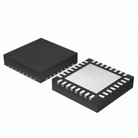
EFM32G200F64 Energy Micro, EFM32G200F64 Datasheet - Page 332

EFM32G200F64
Manufacturer Part Number
EFM32G200F64
Description
MCU 32BIT 64KB FLASH 32-QFN
Manufacturer
Energy Micro
Series
Geckor
Datasheets
1.EFM32G200F16.pdf
(63 pages)
2.EFM32G200F16.pdf
(10 pages)
3.EFM32G200F16.pdf
(463 pages)
4.EFM32G200F16.pdf
(136 pages)
Specifications of EFM32G200F64
Core Processor
ARM® Cortex-M3™
Core Size
32-Bit
Speed
32MHz
Connectivity
EBI/EMI, I²C, IrDA, SmartCard, SPI, UART/USART
Peripherals
Brown-out Detect/Reset, DMA, POR, PWM, WDT
Number Of I /o
24
Program Memory Size
64KB (64K x 8)
Program Memory Type
FLASH
Ram Size
16K x 8
Voltage - Supply (vcc/vdd)
1.8 V ~ 3.8 V
Data Converters
A/D 4x12b, D/A 1x12b
Oscillator Type
External
Operating Temperature
-40°C ~ 85°C
Package / Case
32-VQFN Exposed Pad
Processor Series
EFM32G200
Core
ARM Cortex-M3
Data Bus Width
32 bit
Data Ram Size
16 KB
Interface Type
I2C, UART
Maximum Clock Frequency
32 MHz
Number Of Programmable I/os
24
Number Of Timers
2
Operating Supply Voltage
1.8 V to 3.8 V
Maximum Operating Temperature
+ 85 C
Mounting Style
SMD/SMT
Minimum Operating Temperature
- 40 C
Lead Free Status / RoHS Status
Lead free / RoHS Compliant
Eeprom Size
-
Lead Free Status / Rohs Status
Details
Available stocks
Company
Part Number
Manufacturer
Quantity
Price
- EFM32G200F16 PDF datasheet
- EFM32G200F16 PDF datasheet #2
- EFM32G200F16 PDF datasheet #3
- EFM32G200F16 PDF datasheet #4
- Current page: 332 of 463
- Download datasheet (8Mb)
24.3 Functional Description
24.3.1 Warm-up Time
24.3.2 Response Time
2010-09-06 - d0001_Rev1.00
An overview of the VCMP is shown in Figure 24.1 (p. 332) .
Figure 24.1. VCMP Overview
The comparator has two analog inputs, one positive and one negative. When the comparator is active,
the output indicates which of the two input voltages is higher. When the voltage on the positive input is
higher than the negative input voltage, the digital output is high and vice versa.
The output of the comparator can be read in the VCMPOUT bit in VCMP_STATUS. Configuration
registers should only be changed while the comparator is disabled.
VCMP is enabled by setting the EN bit in VCMP_CTRL. When this bit is set, the comparator must stabilize
before becoming active and the outputs can be used. This time period is called the warm-up time. The
warm-up time is a configurable number of HFPERCLK cycles, set in WARMTIME, which should be set to
at least 10 µs. When the comparator is enabled and warmed up, the VCMPACT bit in VCMP_STATUS
will be set to indicate that the comparator is active.
As long as the comparator is not enabled or not warmed up, VCMPACT will be cleared and the
comparator output value is set to the value in INACTVAL in VCMP_CTRL.
One should wait until the warm-up period is over before entering EM2 or EM3, otherwise no comparator
interrupts will be detected. EM1 can still be entered during warm-up. After the warm-up period is
completed, interrupts will be detected in EM2 and EM3.
There is a delay from when the actual input voltage changes polarity, to when the output toggles. This
period is called the response time and can be altered by increasing or decreasing the bias current to the
comparator through the BIAS and HALFBIAS fields in VCMP_CTRL as shown in Table 24.1 (p. 332)
. Setting a lower bias current will result in lower power consumption, but a longer response time.
Table 24.1. Bias Configuration
BIAS
0b0000
0b0001
0b0010
0b0011
0b0100
0b0101
V
DD
TRIGLEVEL
Scaler
BIASPROG
HALFBIAS
HYSTEN
EN
HALFBIAS=0
0.1
0.2
0.4
0.6
0.8
1.0
Warm -up
counter
LPREF
1.25V
...the world's most energy friendly microcontrollers
332
INACTVAL
VCMPACT
1
0
Read/Write registers
Read only register
Bias Current (µA)
HALFBIAS=1
0.05
0.1
0.2
0.3
0.4
0.5
Warm up interrupt
Edge interrupt
PRS
VCMPOUT
www.energymicro.com
Related parts for EFM32G200F64
Image
Part Number
Description
Manufacturer
Datasheet
Request
R

Part Number:
Description:
KIT STARTER EFM32 GECKO
Manufacturer:
Energy Micro
Datasheet:

Part Number:
Description:
KIT DEV EFM32 GECKO LCD SUPPORT
Manufacturer:
Energy Micro
Datasheet:

Part Number:
Description:
BOARD PROTOTYPING FOR EFM32
Manufacturer:
Energy Micro
Datasheet:

Part Number:
Description:
KIT DEVELOPMENT EFM32 GECKO
Manufacturer:
Energy Micro
Datasheet:

Part Number:
Description:
MCU, MPU & DSP Development Tools TG840 Sample Kit
Manufacturer:
Energy Micro
Datasheet:

Part Number:
Description:
MCU, MPU & DSP Development Tools TG Starter Kit
Manufacturer:
Energy Micro
Datasheet:

Part Number:
Description:
MCU, MPU & DSP Development Tools TG108 Sample Kit
Manufacturer:
Energy Micro

Part Number:
Description:
MCU, MPU & DSP Development Tools TG210 Sample Kit
Manufacturer:
Energy Micro
Datasheet:

Part Number:
Description:
MCU, MPU & DSP Development Tools TG822 Sample Kit
Manufacturer:
Energy Micro
Datasheet:

Part Number:
Description:
MCU, MPU & DSP Development Tools TG230 Sample Kit
Manufacturer:
Energy Micro

Part Number:
Description:
SAMPLE KIT (SMALL BOX - CONTAINING 2 DEVICES)
Manufacturer:
Energy Micro

Part Number:
Description:
SAMPLE KIT (SMALL BOX - CONTAINING 2 DEVICES)
Manufacturer:
Energy Micro


