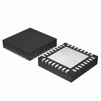
EFM32G200F64 Energy Micro, EFM32G200F64 Datasheet - Page 345

EFM32G200F64
Manufacturer Part Number
EFM32G200F64
Description
MCU 32BIT 64KB FLASH 32-QFN
Manufacturer
Energy Micro
Series
Geckor
Datasheets
1.EFM32G200F16.pdf
(63 pages)
2.EFM32G200F16.pdf
(10 pages)
3.EFM32G200F16.pdf
(463 pages)
4.EFM32G200F16.pdf
(136 pages)
Specifications of EFM32G200F64
Core Processor
ARM® Cortex-M3™
Core Size
32-Bit
Speed
32MHz
Connectivity
EBI/EMI, I²C, IrDA, SmartCard, SPI, UART/USART
Peripherals
Brown-out Detect/Reset, DMA, POR, PWM, WDT
Number Of I /o
24
Program Memory Size
64KB (64K x 8)
Program Memory Type
FLASH
Ram Size
16K x 8
Voltage - Supply (vcc/vdd)
1.8 V ~ 3.8 V
Data Converters
A/D 4x12b, D/A 1x12b
Oscillator Type
External
Operating Temperature
-40°C ~ 85°C
Package / Case
32-VQFN Exposed Pad
Processor Series
EFM32G200
Core
ARM Cortex-M3
Data Bus Width
32 bit
Data Ram Size
16 KB
Interface Type
I2C, UART
Maximum Clock Frequency
32 MHz
Number Of Programmable I/os
24
Number Of Timers
2
Operating Supply Voltage
1.8 V to 3.8 V
Maximum Operating Temperature
+ 85 C
Mounting Style
SMD/SMT
Minimum Operating Temperature
- 40 C
Lead Free Status / RoHS Status
Lead free / RoHS Compliant
Eeprom Size
-
Lead Free Status / Rohs Status
Details
Available stocks
Company
Part Number
Manufacturer
Quantity
Price
- EFM32G200F16 PDF datasheet
- EFM32G200F16 PDF datasheet #2
- EFM32G200F16 PDF datasheet #3
- EFM32G200F16 PDF datasheet #4
- Current page: 345 of 463
- Download datasheet (8Mb)
25.3.7.3 Conversion Tailgating
25.3.7.4 Conversion Trigger
25.3.7.5 Results
2010-09-06 - d0001_Rev1.00
The scan sequence has priority over the single sample mode. However, a scan trigger will not interrupt
in the middle of a single conversion. If a scan sequence is triggered by a timer on a periodic basis,
single sample just before a scan trigger can delay the start of the scan sequence, thus causing jitter in
sample rate. To solve this, conversion tailgating can be chosen by setting TAILGATE in ADCn_CTRL.
When this bit is set, any triggered single samples will wait for the next scan sequence to finish before
activating (see Figure 25.5 (p. 345) ). The single sample will then follow immediately after the scan
sequence. In this way, the scan sequence will always start immediately when triggered, if the period
between the scan triggers is big enough to allow any single samples that might be triggered to finish
in between the scan sequences.
Figure 25.5. ADC Conversion Tailgating
The conversion modes can be activated by writing a 1 to the SINGLESTART or SCANSTART bit
in the ADCn_CMD register. The conversions can be stopped by writing a 1 to the SINGLESTOP or
SCANSTOP bit in the ADCn_CMD register. A START command will have priority over a stop command.
When the ADC is stopped in the middle of a conversion, the result buffer is cleared. The SINGLEACT
and SCANACT bits in ADCn_STATUS are set high when the modes are actively converting or have
pending conversions.
It is also possible to trigger conversions from PRS signals. The system requires one HFPERCLK
cycle pulses to trigger conversions. Setting PRSEN in ADCn_SINGLECTRL/ADCn_SCANCTRL
enables triggering from PRS input. Which PRS channel to listen to is defined by PRSSEL in
ADCn_SINGLECTRL/ADCn_SCANCTRL. When PRS trigger is selected, it is still possible to trigger the
conversion from software. The reader is referred to the PRS datasheet for more information on how to
set up the PRS channels.
Note
The results are presented in 2’s complement form and the format for differential and single ended mode
is given in Table 25.1 (p. 345) and Table 25.2 (p. 346) . If differential mode is selected, the results
are sign extended up to 32-bit (shown in Table 25.4 (p. 347) ).
Table 25.1. ADC Single Ended Conversion
1
0.5
1/4096
0
SINGLESTART
SCANSTART
SINGLEACT
ADC action
SCANACT
Input/Reference
The conversion settings should not be changed while the ADC is running as this can lead to
unpredictable behavior.
Scan
Single
111111111111
011111111111
000000000001
000000000000
...the world's most energy friendly microcontrollers
Binary
345
Scan
Single
Results
FFF
7FF
001
000
Scan
www.energymicro.com
Hex value
Related parts for EFM32G200F64
Image
Part Number
Description
Manufacturer
Datasheet
Request
R

Part Number:
Description:
KIT STARTER EFM32 GECKO
Manufacturer:
Energy Micro
Datasheet:

Part Number:
Description:
KIT DEV EFM32 GECKO LCD SUPPORT
Manufacturer:
Energy Micro
Datasheet:

Part Number:
Description:
BOARD PROTOTYPING FOR EFM32
Manufacturer:
Energy Micro
Datasheet:

Part Number:
Description:
KIT DEVELOPMENT EFM32 GECKO
Manufacturer:
Energy Micro
Datasheet:

Part Number:
Description:
MCU, MPU & DSP Development Tools TG840 Sample Kit
Manufacturer:
Energy Micro
Datasheet:

Part Number:
Description:
MCU, MPU & DSP Development Tools TG Starter Kit
Manufacturer:
Energy Micro
Datasheet:

Part Number:
Description:
MCU, MPU & DSP Development Tools TG108 Sample Kit
Manufacturer:
Energy Micro

Part Number:
Description:
MCU, MPU & DSP Development Tools TG210 Sample Kit
Manufacturer:
Energy Micro
Datasheet:

Part Number:
Description:
MCU, MPU & DSP Development Tools TG822 Sample Kit
Manufacturer:
Energy Micro
Datasheet:

Part Number:
Description:
MCU, MPU & DSP Development Tools TG230 Sample Kit
Manufacturer:
Energy Micro

Part Number:
Description:
SAMPLE KIT (SMALL BOX - CONTAINING 2 DEVICES)
Manufacturer:
Energy Micro

Part Number:
Description:
SAMPLE KIT (SMALL BOX - CONTAINING 2 DEVICES)
Manufacturer:
Energy Micro


