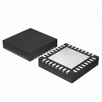
EFM32G200F64 Energy Micro, EFM32G200F64 Datasheet - Page 29

EFM32G200F64
Manufacturer Part Number
EFM32G200F64
Description
MCU 32BIT 64KB FLASH 32-QFN
Manufacturer
Energy Micro
Series
Geckor
Datasheets
1.EFM32G200F16.pdf
(63 pages)
2.EFM32G200F16.pdf
(10 pages)
3.EFM32G200F16.pdf
(463 pages)
4.EFM32G200F16.pdf
(136 pages)
Specifications of EFM32G200F64
Core Processor
ARM® Cortex-M3™
Core Size
32-Bit
Speed
32MHz
Connectivity
EBI/EMI, I²C, IrDA, SmartCard, SPI, UART/USART
Peripherals
Brown-out Detect/Reset, DMA, POR, PWM, WDT
Number Of I /o
24
Program Memory Size
64KB (64K x 8)
Program Memory Type
FLASH
Ram Size
16K x 8
Voltage - Supply (vcc/vdd)
1.8 V ~ 3.8 V
Data Converters
A/D 4x12b, D/A 1x12b
Oscillator Type
External
Operating Temperature
-40°C ~ 85°C
Package / Case
32-VQFN Exposed Pad
Processor Series
EFM32G200
Core
ARM Cortex-M3
Data Bus Width
32 bit
Data Ram Size
16 KB
Interface Type
I2C, UART
Maximum Clock Frequency
32 MHz
Number Of Programmable I/os
24
Number Of Timers
2
Operating Supply Voltage
1.8 V to 3.8 V
Maximum Operating Temperature
+ 85 C
Mounting Style
SMD/SMT
Minimum Operating Temperature
- 40 C
Lead Free Status / RoHS Status
Lead free / RoHS Compliant
Eeprom Size
-
Lead Free Status / Rohs Status
Details
Available stocks
Company
Part Number
Manufacturer
Quantity
Price
- EFM32G200F16 PDF datasheet
- EFM32G200F16 PDF datasheet #2
- EFM32G200F16 PDF datasheet #3
- EFM32G200F16 PDF datasheet #4
- Current page: 29 of 463
- Download datasheet (8Mb)
7.3.1 User Data (UD) Page Description
7.3.2 Lock Bits (LB) Page Description
7.3.3 Device Information (DI) Page
7.3.4 Device Revision
2010-09-06 - d0001_Rev1.00
This is the user data page in the information block. The page can be erased and written by software. The
page is erased by the ERASEPAGE command of the MSC_WRITECMD register. Note that the page is
not erased by a device erase operation. The device erase operation is described in Section 6.4 (p. 23) .
This page contains the following information:
• Main block Page Lock Words (PLWs)
• User data page Lock Word (ULWs)
• Debug Lock Word (DLW)
The words in this page are organized as shown in Table 7.2 (p. 29) :
Table 7.2. Lock Bits Page Structure
There are 32 page lock bits per page lock word (PLW). Bit 0 refers to the first page and bit 31 refers
to the last page within a PLW. Thus, PLW[0] contains lock bits for page 0-31 in the main block, PLW[1]
contains lock bits for page 32-63 etc. A page is locked when the bit is 0. A locked page cannot be erased
or written.
Word 127 is the debug lock word (DLW). Bit 0 of this word is the debug lock bit. If this bit is 1, then
debug access is enabled. Debug access to the core is disabled from power-on reset until the DLW is
evaluated immediately before the Cortex-M3 starts execution of the user application code. If the bit is
0, then debug access to the core remains blocked.
Word 126 is the user page lock word (ULW). Bit 0 of this word is the page lock bit. The lock bits can
be reset by a device erase operation initiated from the Authentication Access Port (AAP) registers. The
AAP is described in more detail in Section 6.4 (p. 23) . Note that the AAP is only accessible from the
debug interface, and cannot be accessed from the Cortex-M3 core.
This read-only page holds oscillator, DAC and ADC calibration data from the production test as well as
an unique device ID. The page is further described in Section 5.6 (p. 21) .
The device revision number is read from the ROM Table. The Revision number is extracted from the
PID2 and PID3 registers, as illustrated in Figure 7.1 (p. 29) .The Rev[7:4] and Rev[3:0] must be
combined to form the complete revision number Revision[7:0].
Figure 7.1. Revision Number Extraction
127
126
N
…
1
0
31:8
PID2 (0 xE0 0 FFFE8 )
Rev[ 7:4]
7:4
3:0
...the world's most energy friendly microcontrollers
31:8
PID3 (0 xE0 0 FFFEC)
29
DLW
ULW
PLW[N]
…
PLW[1]
PLW[0]
Rev[ 3:0]
7:4
3:0
www.energymicro.com
Related parts for EFM32G200F64
Image
Part Number
Description
Manufacturer
Datasheet
Request
R

Part Number:
Description:
KIT STARTER EFM32 GECKO
Manufacturer:
Energy Micro
Datasheet:

Part Number:
Description:
KIT DEV EFM32 GECKO LCD SUPPORT
Manufacturer:
Energy Micro
Datasheet:

Part Number:
Description:
BOARD PROTOTYPING FOR EFM32
Manufacturer:
Energy Micro
Datasheet:

Part Number:
Description:
KIT DEVELOPMENT EFM32 GECKO
Manufacturer:
Energy Micro
Datasheet:

Part Number:
Description:
MCU, MPU & DSP Development Tools TG840 Sample Kit
Manufacturer:
Energy Micro
Datasheet:

Part Number:
Description:
MCU, MPU & DSP Development Tools TG Starter Kit
Manufacturer:
Energy Micro
Datasheet:

Part Number:
Description:
MCU, MPU & DSP Development Tools TG108 Sample Kit
Manufacturer:
Energy Micro

Part Number:
Description:
MCU, MPU & DSP Development Tools TG210 Sample Kit
Manufacturer:
Energy Micro
Datasheet:

Part Number:
Description:
MCU, MPU & DSP Development Tools TG822 Sample Kit
Manufacturer:
Energy Micro
Datasheet:

Part Number:
Description:
MCU, MPU & DSP Development Tools TG230 Sample Kit
Manufacturer:
Energy Micro

Part Number:
Description:
SAMPLE KIT (SMALL BOX - CONTAINING 2 DEVICES)
Manufacturer:
Energy Micro

Part Number:
Description:
SAMPLE KIT (SMALL BOX - CONTAINING 2 DEVICES)
Manufacturer:
Energy Micro


