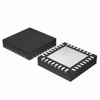
EFM32G200F64 Energy Micro, EFM32G200F64 Datasheet - Page 40

EFM32G200F64
Manufacturer Part Number
EFM32G200F64
Description
MCU 32BIT 64KB FLASH 32-QFN
Manufacturer
Energy Micro
Series
Geckor
Datasheets
1.EFM32G200F16.pdf
(63 pages)
2.EFM32G200F16.pdf
(10 pages)
3.EFM32G200F16.pdf
(463 pages)
4.EFM32G200F16.pdf
(136 pages)
Specifications of EFM32G200F64
Core Processor
ARM® Cortex-M3™
Core Size
32-Bit
Speed
32MHz
Connectivity
EBI/EMI, I²C, IrDA, SmartCard, SPI, UART/USART
Peripherals
Brown-out Detect/Reset, DMA, POR, PWM, WDT
Number Of I /o
24
Program Memory Size
64KB (64K x 8)
Program Memory Type
FLASH
Ram Size
16K x 8
Voltage - Supply (vcc/vdd)
1.8 V ~ 3.8 V
Data Converters
A/D 4x12b, D/A 1x12b
Oscillator Type
External
Operating Temperature
-40°C ~ 85°C
Package / Case
32-VQFN Exposed Pad
Processor Series
EFM32G200
Core
ARM Cortex-M3
Data Bus Width
32 bit
Data Ram Size
16 KB
Interface Type
I2C, UART
Maximum Clock Frequency
32 MHz
Number Of Programmable I/os
24
Number Of Timers
2
Operating Supply Voltage
1.8 V to 3.8 V
Maximum Operating Temperature
+ 85 C
Mounting Style
SMD/SMT
Minimum Operating Temperature
- 40 C
Lead Free Status / RoHS Status
Lead free / RoHS Compliant
Eeprom Size
-
Lead Free Status / Rohs Status
Details
Available stocks
Company
Part Number
Manufacturer
Quantity
Price
- EFM32G200F16 PDF datasheet
- EFM32G200F16 PDF datasheet #2
- EFM32G200F16 PDF datasheet #3
- EFM32G200F16 PDF datasheet #4
- Current page: 40 of 463
- Download datasheet (8Mb)
8.4.1 Channel Select Configuration
8.4.2 DMA control
8.4.2.1 DMA arbitration rate
2010-09-06 - d0001_Rev1.00
off-loading the processor from copying large amounts of data or avoiding frequent interrupts to service
peripherals needing more data or having available data. It can also be used to reduce the system energy
consumption by making the DMA work autonomously with the LEUART for data transfer in EM2 without
having to wake up the processor core from sleep.
The DMA Controller contains 8 independent channels. Each of these channels can be connected to any
of the available peripheral trigger sources by writing to the configuration registers, see Section 8.4.1 (p.
40) . In addition, each channel can be triggered by software (for large memory transfers or for
debugging purposes).
What the DMA Controller should do when one of its channels is triggered, is configured through channel
descriptors residing in system memory. Before enabling a channel, the software must therefore take care
to write this configuration to memory. When the channel is triggered, the DMA Controller will first read
the channel descriptor from system memory, and then it will proceed to perform the memory transfers
as specified by the descriptor. The descriptor contains the memory address to read from, the memory
address to write to, the number of bytes to be transferred, etc. The channel descriptor is described in
detail in Section 8.4.3 (p. 50) .
In addition to the basic transfer mode, the DMA Controller also supports two advanced transfer modes;
ping-pong and scatter-gather. Ping-pong transfers are ideally suited for streaming data for high-speed
peripheral communication as the DMA will be ready to retrieve the next incoming data bytes immediately
while the processor core is still processing the previous ones (and similarly for outgoing communication).
Scatter-gather involves executing a series of tasks from memory, and allows sophisticated schemes to
be implemented by software.
Using different priority levels for the channels and setting the number of bytes after which the DMA
Controller rearbitrates, it is possible to ensure that timing-critical transfers are serviced on time.
The channel select block allows selecting which peripheral's request lines (dma_req, dma_sreq) to
connect to each DMA channel.
This configuration is done by software through the extra registers DMA_CH0_CTRL- DMA_CH7_CTRL,
with SOURCESEL and SIGSEL components. SOURCESEL selects which peripheral to listen to.
SIGSEL selects which of the peripheral’s output signals is selected.
All peripherals are connected to dma_req. When this signal is triggered, the DMA performs a number
of transfers as specified by the channel descriptor (2
dma_sreq line. When only dma_sreq is asserted but not dma_req, then the DMA will perform exactly
one transfer only (given that dma_sreq is enabled by software).
You can configure when the controller arbitrates during a DMA transfer. This enables you to reduce the
latency to service a higher priority channel.
The controller provides four bits that configure how many AHB bus transfers occur before it rearbitrates.
These bits are known as the R_power bits because the value you enter, R, is raised to the power of two
and this determines the arbitration rate. For example, if R = 4 then the arbitration rate is 2
controller arbitrates every 16 DMA transfers.
Table 8.1 (p. 40) lists the arbitration rates.
Table 8.1. AHB bus transfer arbitration interval
R_power
b0000
Arbitrate after x DMA transfers
x = 1
...the world's most energy friendly microcontrollers
40
R
). The USARTs are additionally connected to the
www.energymicro.com
4
, that is, the
Related parts for EFM32G200F64
Image
Part Number
Description
Manufacturer
Datasheet
Request
R

Part Number:
Description:
KIT STARTER EFM32 GECKO
Manufacturer:
Energy Micro
Datasheet:

Part Number:
Description:
KIT DEV EFM32 GECKO LCD SUPPORT
Manufacturer:
Energy Micro
Datasheet:

Part Number:
Description:
BOARD PROTOTYPING FOR EFM32
Manufacturer:
Energy Micro
Datasheet:

Part Number:
Description:
KIT DEVELOPMENT EFM32 GECKO
Manufacturer:
Energy Micro
Datasheet:

Part Number:
Description:
MCU, MPU & DSP Development Tools TG840 Sample Kit
Manufacturer:
Energy Micro
Datasheet:

Part Number:
Description:
MCU, MPU & DSP Development Tools TG Starter Kit
Manufacturer:
Energy Micro
Datasheet:

Part Number:
Description:
MCU, MPU & DSP Development Tools TG108 Sample Kit
Manufacturer:
Energy Micro

Part Number:
Description:
MCU, MPU & DSP Development Tools TG210 Sample Kit
Manufacturer:
Energy Micro
Datasheet:

Part Number:
Description:
MCU, MPU & DSP Development Tools TG822 Sample Kit
Manufacturer:
Energy Micro
Datasheet:

Part Number:
Description:
MCU, MPU & DSP Development Tools TG230 Sample Kit
Manufacturer:
Energy Micro

Part Number:
Description:
SAMPLE KIT (SMALL BOX - CONTAINING 2 DEVICES)
Manufacturer:
Energy Micro

Part Number:
Description:
SAMPLE KIT (SMALL BOX - CONTAINING 2 DEVICES)
Manufacturer:
Energy Micro


