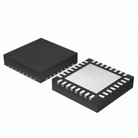
EFM32G200F64 Energy Micro, EFM32G200F64 Datasheet - Page 378

EFM32G200F64
Manufacturer Part Number
EFM32G200F64
Description
MCU 32BIT 64KB FLASH 32-QFN
Manufacturer
Energy Micro
Series
Geckor
Datasheets
1.EFM32G200F16.pdf
(63 pages)
2.EFM32G200F16.pdf
(10 pages)
3.EFM32G200F16.pdf
(463 pages)
4.EFM32G200F16.pdf
(136 pages)
Specifications of EFM32G200F64
Core Processor
ARM® Cortex-M3™
Core Size
32-Bit
Speed
32MHz
Connectivity
EBI/EMI, I²C, IrDA, SmartCard, SPI, UART/USART
Peripherals
Brown-out Detect/Reset, DMA, POR, PWM, WDT
Number Of I /o
24
Program Memory Size
64KB (64K x 8)
Program Memory Type
FLASH
Ram Size
16K x 8
Voltage - Supply (vcc/vdd)
1.8 V ~ 3.8 V
Data Converters
A/D 4x12b, D/A 1x12b
Oscillator Type
External
Operating Temperature
-40°C ~ 85°C
Package / Case
32-VQFN Exposed Pad
Processor Series
EFM32G200
Core
ARM Cortex-M3
Data Bus Width
32 bit
Data Ram Size
16 KB
Interface Type
I2C, UART
Maximum Clock Frequency
32 MHz
Number Of Programmable I/os
24
Number Of Timers
2
Operating Supply Voltage
1.8 V to 3.8 V
Maximum Operating Temperature
+ 85 C
Mounting Style
SMD/SMT
Minimum Operating Temperature
- 40 C
Lead Free Status / RoHS Status
Lead free / RoHS Compliant
Eeprom Size
-
Lead Free Status / Rohs Status
Details
Available stocks
Company
Part Number
Manufacturer
Quantity
Price
- EFM32G200F16 PDF datasheet
- EFM32G200F16 PDF datasheet #2
- EFM32G200F16 PDF datasheet #3
- EFM32G200F16 PDF datasheet #4
- Current page: 378 of 463
- Download datasheet (8Mb)
27.3.1 Encryption/Decryption
27.3.2 Data and Key Access
2010-09-06 - d0001_Rev1.00
Figure 27.1. AES Key and Data Definitions
The AES module can be set to encrypt or decrypt by clearing/setting the DECRYPT bit in AES_CTRL.
The AES256 bit in AES_CTRL configures the size of the key used for encryption/decryption. The
AES_CTRL register should not be altered while AES is running, as this may lead to unpredictable
behaviour.
An AES encryption/decryption can be started in the following ways:
• Writing a 1 to the START bit in AES_CMD
• Writing 4 times 32 bits to AES_DATA when the DATASTART control bit is set
• Writing 4 times 32 bits to AES_XORDATA when the XORSTART control bit is set
An AES encryption/decryption can be stopped by writing a 1 to the STOP bit in AES_CMD. The
RUNNING bit in AES_STATUS indicates that an AES encryption/decryption is ongoing.
The AES module contains a 128-bit DATA (State) register and two 128-bit KEY registers defined as
DATA3-DATA0, KEY3-KEY0 (KEYL) and KEY7-KEY4 (KEYH). In AES128 mode, the 128-bit key is read
from KEYL, while both KEYH and KEYL is used in AES256 mode. See Figure 27.2 (p. 378) . The
figure presents the key byte order for 256-bit keys. In 128-bit mode a
128-bit key.
It is important to note the order of the individual bytes in the key and state in relation to how they are
defined in the Advanced Encryption Standard (FIPS-197).
Figure 27.2. AES Data and Key Orientation as Defined in the Advanced Encryption Standard
The registers DATA3-DATA0, are not memory mapped directly, but can be written/read by accessing
AES_DATA or AES_XORDATA. The same applies for the key registers, KEY3-KEY0 which are
accessed through AES_KEYLn (n=A, B, C or D), while KEY7-KEY4 are accessed through KEYHn
(n=A, B, C or D). Writing DATA3-DATA0 is then done through 4 consecutive writes to AES_DATA (or
AES_XORDATA), starting with the word which is to be written to DATA0. For each write, the words will
PlainText
[ 31:24]
[ 23:16]
PlainKey
[ 15:8]
[ 7:0]
S
S
S
S
0,0
1,0
2,0
3,0
S
S
S
S
DATA
0,1
1,1
2,1
3,1
S
S
S
S
0,2
1,2
2,2
3,2
Decryption
Decryption
Encryption
Encryption
S
S
S
S
0,3
1,3
2,3
3,3
a
a
a
a
0
1
2
3
a
a
a
a
KEYH
4
5
6
7
CipherText
CipherKey
a
a
a
a
10
11
8
9
a
a
a
a
12
13
14
15
a
a
a
a
16
17
18
19
...the world's most energy friendly microcontrollers
378
a
a
a
a
KEYL
20
21
22
23
a
a
a
a
24
25
26
27
a
a
a
a
28
29
30
31
16
represents the first byte of the
www.energymicro.com
Related parts for EFM32G200F64
Image
Part Number
Description
Manufacturer
Datasheet
Request
R

Part Number:
Description:
KIT STARTER EFM32 GECKO
Manufacturer:
Energy Micro
Datasheet:

Part Number:
Description:
KIT DEV EFM32 GECKO LCD SUPPORT
Manufacturer:
Energy Micro
Datasheet:

Part Number:
Description:
BOARD PROTOTYPING FOR EFM32
Manufacturer:
Energy Micro
Datasheet:

Part Number:
Description:
KIT DEVELOPMENT EFM32 GECKO
Manufacturer:
Energy Micro
Datasheet:

Part Number:
Description:
MCU, MPU & DSP Development Tools TG840 Sample Kit
Manufacturer:
Energy Micro
Datasheet:

Part Number:
Description:
MCU, MPU & DSP Development Tools TG Starter Kit
Manufacturer:
Energy Micro
Datasheet:

Part Number:
Description:
MCU, MPU & DSP Development Tools TG108 Sample Kit
Manufacturer:
Energy Micro

Part Number:
Description:
MCU, MPU & DSP Development Tools TG210 Sample Kit
Manufacturer:
Energy Micro
Datasheet:

Part Number:
Description:
MCU, MPU & DSP Development Tools TG822 Sample Kit
Manufacturer:
Energy Micro
Datasheet:

Part Number:
Description:
MCU, MPU & DSP Development Tools TG230 Sample Kit
Manufacturer:
Energy Micro

Part Number:
Description:
SAMPLE KIT (SMALL BOX - CONTAINING 2 DEVICES)
Manufacturer:
Energy Micro

Part Number:
Description:
SAMPLE KIT (SMALL BOX - CONTAINING 2 DEVICES)
Manufacturer:
Energy Micro


