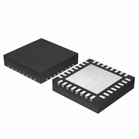
EFM32G200F64 Energy Micro, EFM32G200F64 Datasheet - Page 191

EFM32G200F64
Manufacturer Part Number
EFM32G200F64
Description
MCU 32BIT 64KB FLASH 32-QFN
Manufacturer
Energy Micro
Series
Geckor
Datasheets
1.EFM32G200F16.pdf
(63 pages)
2.EFM32G200F16.pdf
(10 pages)
3.EFM32G200F16.pdf
(463 pages)
4.EFM32G200F16.pdf
(136 pages)
Specifications of EFM32G200F64
Core Processor
ARM® Cortex-M3™
Core Size
32-Bit
Speed
32MHz
Connectivity
EBI/EMI, I²C, IrDA, SmartCard, SPI, UART/USART
Peripherals
Brown-out Detect/Reset, DMA, POR, PWM, WDT
Number Of I /o
24
Program Memory Size
64KB (64K x 8)
Program Memory Type
FLASH
Ram Size
16K x 8
Voltage - Supply (vcc/vdd)
1.8 V ~ 3.8 V
Data Converters
A/D 4x12b, D/A 1x12b
Oscillator Type
External
Operating Temperature
-40°C ~ 85°C
Package / Case
32-VQFN Exposed Pad
Processor Series
EFM32G200
Core
ARM Cortex-M3
Data Bus Width
32 bit
Data Ram Size
16 KB
Interface Type
I2C, UART
Maximum Clock Frequency
32 MHz
Number Of Programmable I/os
24
Number Of Timers
2
Operating Supply Voltage
1.8 V to 3.8 V
Maximum Operating Temperature
+ 85 C
Mounting Style
SMD/SMT
Minimum Operating Temperature
- 40 C
Lead Free Status / RoHS Status
Lead free / RoHS Compliant
Eeprom Size
-
Lead Free Status / Rohs Status
Details
Available stocks
Company
Part Number
Manufacturer
Quantity
Price
- EFM32G200F16 PDF datasheet
- EFM32G200F16 PDF datasheet #2
- EFM32G200F16 PDF datasheet #3
- EFM32G200F16 PDF datasheet #4
- Current page: 191 of 463
- Download datasheet (8Mb)
16.3.3 Synchronous Operation
16.3.3.1 Frame Format
16.3.3.2 Clock Generation
2010-09-06 - d0001_Rev1.00
Figure 16.14. USART SmartCard Stop Bit Sampling
For communication with a SmartCard, a clock signal needs to be generated for the card. This clock
output can be generated using one of the timers. See the ISO 7816 specification for more info on this
clock signal.
SmartCard T1 mode is also supported. The T1 frame format used is the same as the asynchronous
frame format with parity bit enabled and one stop bit. The USART must then be configured to operate
in asynchronous half duplex mode.
Most of the features in asynchronous mode are available in synchronous mode. Multi-processor mode
can be enabled for 9-bit frames, loopback is available and collision detection can be performed.
The frames used in synchronous mode need no start and stop bits since a single clock is available to
all parts participating in the communication. Parity bits cannot be used in synchronous mode.
The USART supports frame lengths of 4 to 16 bits per frame. Larger frames can be simulated by
transmitting multiple smaller frames, i.e. a 22 bit frame can be sent using two 11-bit frames, and a 21
bit frame can be generated by transmitting three 7-bit frames. The number of bits in a frame is set using
DATABITS in USARTn_FRAME.
The frames in synchronous mode are by default transmitted with the least significant bit first like in
asynchronous mode. The bit-order can be reversed by setting MSBF in USARTn_CTRL.
The frame format used by the transmitter can be inverted by setting TXINV in USARTn_CTRL, and the
format expected by the receiver can be inverted by setting RXINV, also in USARTn_CTRL.
The bit-rate in synchronous mode is given by Equation 16.3 (p. 191) . As in the case of asynchronous
operation, the clock division factor have a 13-bit integral part and a 2-bit fractional part.
USART Synchronous Mode Bit Rate
Given a desired baud rate brdesired, the clock divider USARTn_CLKDIV can be calculated using
Equation 16.4 (p. 192)
13 14 15 16 1
7
4
6
P
8
1
1
1
2
br = f
3
2
1/2 stop bit
2
HFPERCLK
4
5
3
2
6
3
/(2 x (1 + USARTn_CLKDIV/256))
7
4
8
9 10 11
5
4
3
NAK or stop
...the world's most energy friendly microcontrollers
6
191
5
12
13
7
4
14 15 16
6
8
17 18 X
9
7
5
10
8
X
www.energymicro.com
X
X
x
X
x
X
X
X
Stop
(16.3)
Related parts for EFM32G200F64
Image
Part Number
Description
Manufacturer
Datasheet
Request
R

Part Number:
Description:
KIT STARTER EFM32 GECKO
Manufacturer:
Energy Micro
Datasheet:

Part Number:
Description:
KIT DEV EFM32 GECKO LCD SUPPORT
Manufacturer:
Energy Micro
Datasheet:

Part Number:
Description:
BOARD PROTOTYPING FOR EFM32
Manufacturer:
Energy Micro
Datasheet:

Part Number:
Description:
KIT DEVELOPMENT EFM32 GECKO
Manufacturer:
Energy Micro
Datasheet:

Part Number:
Description:
MCU, MPU & DSP Development Tools TG840 Sample Kit
Manufacturer:
Energy Micro
Datasheet:

Part Number:
Description:
MCU, MPU & DSP Development Tools TG Starter Kit
Manufacturer:
Energy Micro
Datasheet:

Part Number:
Description:
MCU, MPU & DSP Development Tools TG108 Sample Kit
Manufacturer:
Energy Micro

Part Number:
Description:
MCU, MPU & DSP Development Tools TG210 Sample Kit
Manufacturer:
Energy Micro
Datasheet:

Part Number:
Description:
MCU, MPU & DSP Development Tools TG822 Sample Kit
Manufacturer:
Energy Micro
Datasheet:

Part Number:
Description:
MCU, MPU & DSP Development Tools TG230 Sample Kit
Manufacturer:
Energy Micro

Part Number:
Description:
SAMPLE KIT (SMALL BOX - CONTAINING 2 DEVICES)
Manufacturer:
Energy Micro

Part Number:
Description:
SAMPLE KIT (SMALL BOX - CONTAINING 2 DEVICES)
Manufacturer:
Energy Micro


