LFEBS12UB Freescale Semiconductor, LFEBS12UB Datasheet - Page 94
LFEBS12UB
Manufacturer Part Number
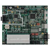
LFEBS12UB
Description
KIT STUDENT LEARNING S12 DG128
Manufacturer
Freescale Semiconductor
Specifications of LFEBS12UB
Architecture
8/16-bit
Code Gen Tools Included
Code Warrior
Silicon Manufacturer
Freescale
Core Architecture
S12
Core Sub-architecture
S12
Silicon Core Number
MC9S12
Silicon Family Name
S12D
Kit Contents
HCS12 DG128 Learning Kit
Rohs Compliant
Yes
Lead Free Status / RoHS Status
Lead free / RoHS Compliant


Chapter 2 Port Integration Module (S12XEPIMV1)
Most I/O pins can be configured by register bits to select data direction and drive strength, to enable and
select pull-up or pull-down devices.
2.1.2
The Port Integration Module includes these distinctive registers:
A standard port pin has the following minimum features:
Optional features supported on dedicated pins:
2.2
This section lists and describes the signals that do connect off-chip.
94
•
•
•
•
•
•
•
•
•
•
•
•
•
•
•
•
•
•
Open drain for wired-or connections
Interrupt inputs with glitch filtering
Reduced input threshold to support low voltage applications
Port F associated with IIC, SCI and chip select outputs
Data and data direction registers for Ports A, B, C, D, E, K, T, S, M, P, H, J, AD0, AD1, R, L, and
F when used as general-purpose I/O
Control registers to enable/disable pull-device and select pull-ups/pull-downs on Ports T, S, M, P,
H, J, R, L, and F on per-pin basis
Control registers to enable/disable pull-up devices on Ports AD0 and AD1 on per-pin basis
Single control register to enable/disable pull-ups on Ports A, B, C, D, E, and K on per-port basis
and on BKGD pin
Control registers to enable/disable reduced output drive on Ports T, S, M, P, H, J, AD0, AD1, R, L,
and F on per-pin basis
Single control register to enable/disable reduced output drive on Ports A, B, C, D, E, and K on per-
port basis
Control registers to enable/disable open-drain (wired-or) mode on Ports S, M, and L
Interrupt flag register for pin interrupts on Ports P, H, and J
Control register to configure IRQ pin operation
Free-running clock outputs
Input/output selection
5V output drive with two selectable drive strengths
5V digital and analog input
Input with selectable pull-up or pull-down device
External Signal Description
Features
This document assumes the availability of all features (208-pin package
option). Some functions are not available on lower pin count package
options. Refer to the pin-out summary in the SOC Guide.
MC9S12XE-Family Reference Manual , Rev. 1.23
NOTE
Freescale Semiconductor
Related parts for LFEBS12UB
Image
Part Number
Description
Manufacturer
Datasheet
Request
R

Part Number:
Description:
Manufacturer:
Freescale Semiconductor, Inc
Datasheet:
Part Number:
Description:
Manufacturer:
Freescale Semiconductor, Inc
Datasheet:
Part Number:
Description:
Manufacturer:
Freescale Semiconductor, Inc
Datasheet:
Part Number:
Description:
Manufacturer:
Freescale Semiconductor, Inc
Datasheet:
Part Number:
Description:
Manufacturer:
Freescale Semiconductor, Inc
Datasheet:
Part Number:
Description:
Manufacturer:
Freescale Semiconductor, Inc
Datasheet:
Part Number:
Description:
Manufacturer:
Freescale Semiconductor, Inc
Datasheet:
Part Number:
Description:
Manufacturer:
Freescale Semiconductor, Inc
Datasheet:
Part Number:
Description:
Manufacturer:
Freescale Semiconductor, Inc
Datasheet:
Part Number:
Description:
Manufacturer:
Freescale Semiconductor, Inc
Datasheet:
Part Number:
Description:
Manufacturer:
Freescale Semiconductor, Inc
Datasheet:
Part Number:
Description:
Manufacturer:
Freescale Semiconductor, Inc
Datasheet:
Part Number:
Description:
Manufacturer:
Freescale Semiconductor, Inc
Datasheet:
Part Number:
Description:
Manufacturer:
Freescale Semiconductor, Inc
Datasheet:
Part Number:
Description:
Manufacturer:
Freescale Semiconductor, Inc
Datasheet: