LFEBS12UB Freescale Semiconductor, LFEBS12UB Datasheet - Page 194
LFEBS12UB
Manufacturer Part Number
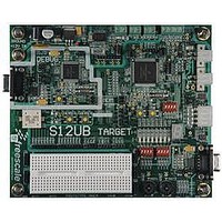
LFEBS12UB
Description
KIT STUDENT LEARNING S12 DG128
Manufacturer
Freescale Semiconductor
Specifications of LFEBS12UB
Architecture
8/16-bit
Code Gen Tools Included
Code Warrior
Silicon Manufacturer
Freescale
Core Architecture
S12
Core Sub-architecture
S12
Silicon Core Number
MC9S12
Silicon Family Name
S12D
Kit Contents
HCS12 DG128 Learning Kit
Rohs Compliant
Yes
Lead Free Status / RoHS Status
Lead free / RoHS Compliant


Chapter 3 Memory Mapping Control (S12XMMCV4)
3.1.5
Figure 3-1
3.2
The user is advised to refer to the device overview for port configuration and location of external bus
signals. Some pins may not be bonded out in all implementations.
Table 3-3
operation.
1. Doted blocks and lines are optional. Please refer to the Device User Guide for their availlibilities.
194
Because of an order from the United States International Trade Commission, BGA-packaged product lines and partnumbers
indicated here currently are not available from Freescale for import or sale in the United States prior to September 2010
•
•
EEEPROM
FLASH
Expanded modes
Address, data, and control signals are activated in normal expanded and special test modes when
accessing the external bus. Access to internal resources will not cause activity on the external bus.
Emulation modes
External bus is active to emulate, via an external tool, the normal expanded or the normal single
chip mode.}
External Signal Description
and
1
Block Diagram
shows a block diagram of the MMC.
Table 3-4
outline the pin names and functions. It also provides a brief description of their
MMC
BDM
MC9S12XE-Family Reference Manual , Rev. 1.23
EBI
Figure 3-1. MMC Block Diagram
Address Decoder & Priority
Target Bus Controller
CPU
RAM
XGATE
Peripherals
FLEXRAY
Freescale Semiconductor
DBG
Related parts for LFEBS12UB
Image
Part Number
Description
Manufacturer
Datasheet
Request
R

Part Number:
Description:
Manufacturer:
Freescale Semiconductor, Inc
Datasheet:
Part Number:
Description:
Manufacturer:
Freescale Semiconductor, Inc
Datasheet:
Part Number:
Description:
Manufacturer:
Freescale Semiconductor, Inc
Datasheet:
Part Number:
Description:
Manufacturer:
Freescale Semiconductor, Inc
Datasheet:
Part Number:
Description:
Manufacturer:
Freescale Semiconductor, Inc
Datasheet:
Part Number:
Description:
Manufacturer:
Freescale Semiconductor, Inc
Datasheet:
Part Number:
Description:
Manufacturer:
Freescale Semiconductor, Inc
Datasheet:
Part Number:
Description:
Manufacturer:
Freescale Semiconductor, Inc
Datasheet:
Part Number:
Description:
Manufacturer:
Freescale Semiconductor, Inc
Datasheet:
Part Number:
Description:
Manufacturer:
Freescale Semiconductor, Inc
Datasheet:
Part Number:
Description:
Manufacturer:
Freescale Semiconductor, Inc
Datasheet:
Part Number:
Description:
Manufacturer:
Freescale Semiconductor, Inc
Datasheet:
Part Number:
Description:
Manufacturer:
Freescale Semiconductor, Inc
Datasheet:
Part Number:
Description:
Manufacturer:
Freescale Semiconductor, Inc
Datasheet:
Part Number:
Description:
Manufacturer:
Freescale Semiconductor, Inc
Datasheet: