LFEBS12UB Freescale Semiconductor, LFEBS12UB Datasheet - Page 769
LFEBS12UB
Manufacturer Part Number
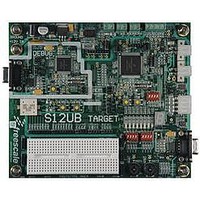
LFEBS12UB
Description
KIT STUDENT LEARNING S12 DG128
Manufacturer
Freescale Semiconductor
Specifications of LFEBS12UB
Architecture
8/16-bit
Code Gen Tools Included
Code Warrior
Silicon Manufacturer
Freescale
Core Architecture
S12
Core Sub-architecture
S12
Silicon Core Number
MC9S12
Silicon Family Name
S12D
Kit Contents
HCS12 DG128 Learning Kit
Rohs Compliant
Yes
Lead Free Status / RoHS Status
Lead free / RoHS Compliant


1. n is used later in this document as a placeholder for the selected transfer width.
Freescale Semiconductor
Because of an order from the United States International Trade Commission, BGA-packaged product lines and partnumbers
MODFEN
SPISWAI
BIDIROE
XFRW
indicated here currently are not available from Freescale for import or sale in the United States prior to September 2010
SPC0
Field
6
4
3
1
0
Transfer Width — This bit is used for selecting the data transfer width. If 8-bit transfer width is selected, SPIDRL
becomes the dedicated data register and SPIDRH is unused. If 16-bit transfer width is selected, SPIDRH and
SPIDRL form a 16-bit data register. Please refer to
information about transmit/receive data handling and the interrupt flag clearing mechanism. In master mode, a
change of this bit will abort a transmission in progress and force the SPI system into idle state.
0 8-bit Transfer Width (n = 8)
1 16-bit Transfer Width (n = 16)
Mode Fault Enable Bit — This bit allows the MODF failure to be detected. If the SPI is in master mode and
MODFEN is cleared, then the SS port pin is not used by the SPI. In slave mode, the SS is available only as an
input regardless of the value of MODFEN. For an overview on the impact of the MODFEN bit on the SS port pin
configuration, refer to
force the SPI system into idle state.
0 SS port pin is not used by the SPI.
1 SS port pin with MODF feature.
Output Enable in the Bidirectional Mode of Operation — This bit controls the MOSI and MISO output buffer
of the SPI, when in bidirectional mode of operation (SPC0 is set). In master mode, this bit controls the output
buffer of the MOSI port, in slave mode it controls the output buffer of the MISO port. In master mode, with SPC0
set, a change of this bit will abort a transmission in progress and force the SPI into idle state.
0 Output buffer disabled.
1 Output buffer enabled.
SPI Stop in Wait Mode Bit — This bit is used for power conservation while in wait mode.
0 SPI clock operates normally in wait mode.
1 Stop SPI clock generation when in wait mode.
Serial Pin Control Bit 0 — This bit enables bidirectional pin configurations as shown in
mode, a change of this bit will abort a transmission in progress and force the SPI system into idle state.
Bidirectional
Bidirectional
Pin Mode
Normal
Normal
SPC0
0
1
0
1
Table 21-5. Bidirectional Pin Configurations
Table
MC9S12XE-Family Reference Manual Rev. 1.23
Table 21-4. SPICR2 Field Descriptions
BIDIROE
21-3. In master mode, a change of this bit will abort a transmission in progress and
(1)
X
X
0
1
0
1
1
Master Mode of Operation
Slave Mode of Operation
MISO not used by SPI
Slave Out
Master In
Slave I/O
Description
Slave In
MISO
Section 21.3.2.4, “SPI Status Register (SPISR)
Chapter 21 Serial Peripheral Interface (S12SPIV5)
MOSI not used by SPI
Master Out
Master I/O
Master In
Slave In
MOSI
Table
21-5. In master
for
769
Related parts for LFEBS12UB
Image
Part Number
Description
Manufacturer
Datasheet
Request
R

Part Number:
Description:
Manufacturer:
Freescale Semiconductor, Inc
Datasheet:
Part Number:
Description:
Manufacturer:
Freescale Semiconductor, Inc
Datasheet:
Part Number:
Description:
Manufacturer:
Freescale Semiconductor, Inc
Datasheet:
Part Number:
Description:
Manufacturer:
Freescale Semiconductor, Inc
Datasheet:
Part Number:
Description:
Manufacturer:
Freescale Semiconductor, Inc
Datasheet:
Part Number:
Description:
Manufacturer:
Freescale Semiconductor, Inc
Datasheet:
Part Number:
Description:
Manufacturer:
Freescale Semiconductor, Inc
Datasheet:
Part Number:
Description:
Manufacturer:
Freescale Semiconductor, Inc
Datasheet:
Part Number:
Description:
Manufacturer:
Freescale Semiconductor, Inc
Datasheet:
Part Number:
Description:
Manufacturer:
Freescale Semiconductor, Inc
Datasheet:
Part Number:
Description:
Manufacturer:
Freescale Semiconductor, Inc
Datasheet:
Part Number:
Description:
Manufacturer:
Freescale Semiconductor, Inc
Datasheet:
Part Number:
Description:
Manufacturer:
Freescale Semiconductor, Inc
Datasheet:
Part Number:
Description:
Manufacturer:
Freescale Semiconductor, Inc
Datasheet:
Part Number:
Description:
Manufacturer:
Freescale Semiconductor, Inc
Datasheet: