LFEBS12UB Freescale Semiconductor, LFEBS12UB Datasheet - Page 700
LFEBS12UB
Manufacturer Part Number
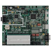
LFEBS12UB
Description
KIT STUDENT LEARNING S12 DG128
Manufacturer
Freescale Semiconductor
Specifications of LFEBS12UB
Architecture
8/16-bit
Code Gen Tools Included
Code Warrior
Silicon Manufacturer
Freescale
Core Architecture
S12
Core Sub-architecture
S12
Silicon Core Number
MC9S12
Silicon Family Name
S12D
Kit Contents
HCS12 DG128 Learning Kit
Rohs Compliant
Yes
Lead Free Status / RoHS Status
Lead free / RoHS Compliant


Chapter 19 Pulse-Width Modulator (S12PWM8B8CV1)
19.3.2.2
The starting polarity of each PWM channel waveform is determined by the associated PPOLx bit in the
PWMPOL register. If the polarity bit is one, the PWM channel output is high at the beginning of the cycle
and then goes low when the duty count is reached. Conversely, if the polarity bit is zero, the output starts
low and then goes high when the duty count is reached.
Read: Anytime
Write: Anytime
700
Module Base + 0x0001
Because of an order from the United States International Trade Commission, BGA-packaged product lines and partnumbers
PPOL[7:0]
PWME2
PWME1
PWME0
Reset
indicated here currently are not available from Freescale for import or sale in the United States prior to September 2010
Field
Field
7–0
2
1
0
W
R
PPOL7
Pulse Width Channel 2 Enable
0 Pulse width channel 2 is disabled.
1 Pulse width channel 2 is enabled. The pulse modulated signal becomes available at PWM, output bit 2 when
Pulse Width Channel 1 Enable
0 Pulse width channel 1 is disabled.
1 Pulse width channel 1 is enabled. The pulse modulated signal becomes available at PWM, output bit 1 when
Pulse Width Channel 0 Enable
0 Pulse width channel 0 is disabled.
1 Pulse width channel 0 is enabled. The pulse modulated signal becomes available at PWM, output bit 0 when
Pulse Width Channel 7–0 Polarity Bits
0 PWM channel 7–0 outputs are low at the beginning of the period, then go high when the duty count is
1 PWM channel 7–0 outputs are high at the beginning of the period, then go low when the duty count is
PWM Polarity Register (PWMPOL)
0
7
PPOLx register bits can be written anytime. If the polarity is changed while
a PWM signal is being generated, a truncated or stretched pulse can occur
during the transition
its clock source begins its next cycle. If CON23 = 1, then bit has no effect and PWM output bit2 is disabled.
its clock source begins its next cycle. If CON01 = 1, then bit has no effect and PWM output line0 is disabled.
reached.
reached.
its clock source begins its next cycle.
PPOL6
0
6
Figure 19-4. PWM Polarity Register (PWMPOL)
MC9S12XE-Family Reference Manual , Rev. 1.23
PPOL5
5
0
PPOL4
NOTE
0
4
Description
Description
PPOL3
0
3
PPOL2
2
0
Freescale Semiconductor
PPOL1
0
1
PPOL0
0
0
Related parts for LFEBS12UB
Image
Part Number
Description
Manufacturer
Datasheet
Request
R

Part Number:
Description:
Manufacturer:
Freescale Semiconductor, Inc
Datasheet:
Part Number:
Description:
Manufacturer:
Freescale Semiconductor, Inc
Datasheet:
Part Number:
Description:
Manufacturer:
Freescale Semiconductor, Inc
Datasheet:
Part Number:
Description:
Manufacturer:
Freescale Semiconductor, Inc
Datasheet:
Part Number:
Description:
Manufacturer:
Freescale Semiconductor, Inc
Datasheet:
Part Number:
Description:
Manufacturer:
Freescale Semiconductor, Inc
Datasheet:
Part Number:
Description:
Manufacturer:
Freescale Semiconductor, Inc
Datasheet:
Part Number:
Description:
Manufacturer:
Freescale Semiconductor, Inc
Datasheet:
Part Number:
Description:
Manufacturer:
Freescale Semiconductor, Inc
Datasheet:
Part Number:
Description:
Manufacturer:
Freescale Semiconductor, Inc
Datasheet:
Part Number:
Description:
Manufacturer:
Freescale Semiconductor, Inc
Datasheet:
Part Number:
Description:
Manufacturer:
Freescale Semiconductor, Inc
Datasheet:
Part Number:
Description:
Manufacturer:
Freescale Semiconductor, Inc
Datasheet:
Part Number:
Description:
Manufacturer:
Freescale Semiconductor, Inc
Datasheet:
Part Number:
Description:
Manufacturer:
Freescale Semiconductor, Inc
Datasheet: