LFEBS12UB Freescale Semiconductor, LFEBS12UB Datasheet - Page 761
LFEBS12UB
Manufacturer Part Number
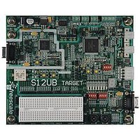
LFEBS12UB
Description
KIT STUDENT LEARNING S12 DG128
Manufacturer
Freescale Semiconductor
Specifications of LFEBS12UB
Architecture
8/16-bit
Code Gen Tools Included
Code Warrior
Silicon Manufacturer
Freescale
Core Architecture
S12
Core Sub-architecture
S12
Silicon Core Number
MC9S12
Silicon Family Name
S12D
Kit Contents
HCS12 DG128 Learning Kit
Rohs Compliant
Yes
Lead Free Status / RoHS Status
Lead free / RoHS Compliant


20.5.3.1
The SCI only originates interrupt requests. The following is a description of how the SCI makes a request
and how the MCU should acknowledge that request. The interrupt vector offset and interrupt number are
chip dependent. The SCI only has a single interrupt line (SCI Interrupt Signal, active high operation) and
all the following interrupts, when generated, are ORed together and issued through that port.
20.5.3.1.1
The TDRE interrupt is set high by the SCI when the transmit shift register receives a byte from the SCI
data register. A TDRE interrupt indicates that the transmit data register (SCIDRH/L) is empty and that a
new byte can be written to the SCIDRH/L for transmission.Clear TDRE by reading SCI status register 1
with TDRE set and then writing to SCI data register low (SCIDRL).
20.5.3.1.2
The TC interrupt is set by the SCI when a transmission has been completed. Transmission is completed
when all bits including the stop bit (if transmitted) have been shifted out and no data is queued to be
transmitted. No stop bit is transmitted when sending a break character and the TC flag is set (providing
there is no more data queued for transmission) when the break character has been shifted out. A TC
interrupt indicates that there is no transmission in progress. TC is set high when the TDRE flag is set and
no data, preamble, or break character is being transmitted. When TC is set, the TXD pin becomes idle
(logic 1). Clear TC by reading SCI status register 1 (SCISR1) with TC set and then writing to SCI data
register low (SCIDRL).TC is cleared automatically when data, preamble, or break is queued and ready to
be sent.
20.5.3.1.3
The RDRF interrupt is set when the data in the receive shift register transfers to the SCI data register. A
RDRF interrupt indicates that the received data has been transferred to the SCI data register and that the
byte can now be read by the MCU. The RDRF interrupt is cleared by reading the SCI status register one
(SCISR1) and then reading SCI data register low (SCIDRL).
20.5.3.1.4
The OR interrupt is set when software fails to read the SCI data register before the receive shift register
receives the next frame. The newly acquired data in the shift register will be lost in this case, but the data
already in the SCI data registers is not affected. The OR interrupt is cleared by reading the SCI status
register one (SCISR1) and then reading SCI data register low (SCIDRL).
20.5.3.1.5
The IDLE interrupt is set when 10 consecutive logic 1s (if M = 0) or 11 consecutive logic 1s (if M = 1)
appear on the receiver input. Once the IDLE is cleared, a valid frame must again set the RDRF flag before
an idle condition can set the IDLE flag. Clear IDLE by reading SCI status register 1 (SCISR1) with IDLE
set and then reading SCI data register low (SCIDRL).
Freescale Semiconductor
Because of an order from the United States International Trade Commission, BGA-packaged product lines and partnumbers
indicated here currently are not available from Freescale for import or sale in the United States prior to September 2010
Description of Interrupt Operation
TDRE Description
TC Description
RDRF Description
OR Description
IDLE Description
MC9S12XE-Family Reference Manual Rev. 1.23
Chapter 20 Serial Communication Interface (S12SCIV5)
761
Related parts for LFEBS12UB
Image
Part Number
Description
Manufacturer
Datasheet
Request
R

Part Number:
Description:
Manufacturer:
Freescale Semiconductor, Inc
Datasheet:
Part Number:
Description:
Manufacturer:
Freescale Semiconductor, Inc
Datasheet:
Part Number:
Description:
Manufacturer:
Freescale Semiconductor, Inc
Datasheet:
Part Number:
Description:
Manufacturer:
Freescale Semiconductor, Inc
Datasheet:
Part Number:
Description:
Manufacturer:
Freescale Semiconductor, Inc
Datasheet:
Part Number:
Description:
Manufacturer:
Freescale Semiconductor, Inc
Datasheet:
Part Number:
Description:
Manufacturer:
Freescale Semiconductor, Inc
Datasheet:
Part Number:
Description:
Manufacturer:
Freescale Semiconductor, Inc
Datasheet:
Part Number:
Description:
Manufacturer:
Freescale Semiconductor, Inc
Datasheet:
Part Number:
Description:
Manufacturer:
Freescale Semiconductor, Inc
Datasheet:
Part Number:
Description:
Manufacturer:
Freescale Semiconductor, Inc
Datasheet:
Part Number:
Description:
Manufacturer:
Freescale Semiconductor, Inc
Datasheet:
Part Number:
Description:
Manufacturer:
Freescale Semiconductor, Inc
Datasheet:
Part Number:
Description:
Manufacturer:
Freescale Semiconductor, Inc
Datasheet:
Part Number:
Description:
Manufacturer:
Freescale Semiconductor, Inc
Datasheet: