LFEBS12UB Freescale Semiconductor, LFEBS12UB Datasheet - Page 333
LFEBS12UB
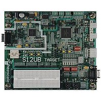
Manufacturer Part Number
LFEBS12UB
Description
KIT STUDENT LEARNING S12 DG128
Manufacturer
Freescale Semiconductor
Specifications of LFEBS12UB
Architecture
8/16-bit
Code Gen Tools Included
Code Warrior
Silicon Manufacturer
Freescale
Core Architecture
S12
Core Sub-architecture
S12
Silicon Core Number
MC9S12
Silicon Family Name
S12D
Kit Contents
HCS12 DG128 Learning Kit
Rohs Compliant
Yes
Lead Free Status / RoHS Status
Lead free / RoHS Compliant


When comparing the XGATE address bus in outside range mode, the initial vector fetch as determined by
the vector contained in the XGATE XGVBR register should be taken into consideration. The XGVBR
register and hence vector address can be modified.
8.4.3
Trigger modes are used as qualifiers for a state sequencer change of state. The control logic determines the
trigger mode and provides a trigger to the state sequencer. The individual trigger modes are described in
the following sections.
8.4.3.1
If a forced trigger comparator match occurs, the trigger immediately initiates a transition to the next state
sequencer state whereby the corresponding flags in DBGSR are set. The state control register for the
current state determines the next state for each trigger. Forced triggers are generated as soon as the
matching address appears on the address bus, which in the case of opcode fetches occurs several cycles
before the opcode execution. For this reason a forced trigger at an opcode address precedes a tagged trigger
at the same address by several cycles.
8.4.3.2
If a CPU12X or XGATE taghit occurs, a transition to another state sequencer state is initiated and the
corresponding DBGSR flags are set. For a comparator related taghit to occur, the S12XDBG must first
generate tags based on comparator matches. When the tagged instruction reaches the execution stage of
the instruction queue a taghit is generated by the CPU12X/XGATE. The state control register for the
current state determines the next state for each trigger.
8.4.3.3
The TAGLO and TAGHI pins (mapped to device pins) can be used to tag an instruction. This function can
be used as another breakpoint source. When the tagged opcode reaches the execution stage of the
instruction queue a transition to the disarmed state0 occurs, ending the debug session and generating a
breakpoint, if breakpoints are enabled. External tagging is only possible in device emulation modes.
8.4.3.4
The XGATE S/W breakpoint request issues a forced breakpoint request to the CPU12X immediately and
triggers the state sequencer into the disarmed state. Active tracing sessions are terminated immediately,
thus if tracing has not yet begun, no trace information is stored. XGATE generated breakpoints are
independent of the DBGBRK bits. The XGSBPE bit in DBGC1 determines if the XGATE S/W breakpoint
function is enabled. The BDM bit in DBGC1 determines if the XGATE requested breakpoint causes the
system to enter BDM Mode or initiate a software interrupt (SWI).
8.4.3.5
Independent of comparator matches or external tag signals it is possible to initiate a tracing session and/or
breakpoint by writing the TRIG bit in DBGC1 to a logic “1”. If configured for begin or mid aligned tracing,
Freescale Semiconductor
Because of an order from the United States International Trade Commission, BGA-packaged product lines and partnumbers
indicated here currently are not available from Freescale for import or sale in the United States prior to September 2010
Trigger Modes
Forced Trigger On Comparator Match
Trigger On Comparator Related Taghit
External Tagging Trigger
Trigger On XGATE S/W Breakpoint Request
TRIG Immediate Trigger
MC9S12XE-Family Reference Manual Rev. 1.23
Chapter 8 S12X Debug (S12XDBGV3) Module
333
Related parts for LFEBS12UB
Image
Part Number
Description
Manufacturer
Datasheet
Request
R

Part Number:
Description:
Manufacturer:
Freescale Semiconductor, Inc
Datasheet:
Part Number:
Description:
Manufacturer:
Freescale Semiconductor, Inc
Datasheet:
Part Number:
Description:
Manufacturer:
Freescale Semiconductor, Inc
Datasheet:
Part Number:
Description:
Manufacturer:
Freescale Semiconductor, Inc
Datasheet:
Part Number:
Description:
Manufacturer:
Freescale Semiconductor, Inc
Datasheet:
Part Number:
Description:
Manufacturer:
Freescale Semiconductor, Inc
Datasheet:
Part Number:
Description:
Manufacturer:
Freescale Semiconductor, Inc
Datasheet:
Part Number:
Description:
Manufacturer:
Freescale Semiconductor, Inc
Datasheet:
Part Number:
Description:
Manufacturer:
Freescale Semiconductor, Inc
Datasheet:
Part Number:
Description:
Manufacturer:
Freescale Semiconductor, Inc
Datasheet:
Part Number:
Description:
Manufacturer:
Freescale Semiconductor, Inc
Datasheet:
Part Number:
Description:
Manufacturer:
Freescale Semiconductor, Inc
Datasheet:
Part Number:
Description:
Manufacturer:
Freescale Semiconductor, Inc
Datasheet:
Part Number:
Description:
Manufacturer:
Freescale Semiconductor, Inc
Datasheet:
Part Number:
Description:
Manufacturer:
Freescale Semiconductor, Inc
Datasheet: