LFEBS12UB Freescale Semiconductor, LFEBS12UB Datasheet - Page 86
LFEBS12UB
Manufacturer Part Number
LFEBS12UB
Description
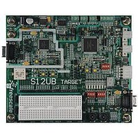
KIT STUDENT LEARNING S12 DG128
Manufacturer
Freescale Semiconductor
Specifications of LFEBS12UB
Architecture
8/16-bit
Code Gen Tools Included
Code Warrior
Silicon Manufacturer
Freescale
Core Architecture
S12
Core Sub-architecture
S12
Silicon Core Number
MC9S12
Silicon Family Name
S12D
Kit Contents
HCS12 DG128 Learning Kit
Rohs Compliant
Yes
Lead Free Status / RoHS Status
Lead free / RoHS Compliant


Chapter 1 Device Overview MC9S12XE-Family
1.7
1.7.1
The ADC module includes four external trigger inputs ETRIG0, ETRIG1, ETRIG2, and ETRIG3. The
external trigger allows the user to synchronize ADC conversion to external trigger events.
shows the connection of the external trigger inputs.
Consult the ATD block description for information about the analog-to-digital converter module. ATD
block description refererences to freeze mode are equivalent to active BDM mode.
1.7.2
Further to the 16 externally available channels, ADC0 features an extra channel[17] that is connected to
the internal temperature sensor at device level. To access this channel ADC0 must use the channel
encoding SC:CD:CC:CB:CA = 1:0:0:0:1 in ATDCTL5. For more temperature sensor information, please
refer to
1.8
The ADC module includes four external trigger inputs ETRIG0, ETRIG1, ETRIG2, and ETRIG3. The
external trigger feature allows the user to synchronize ADC conversion to external trigger events.
18
Consult the ADC block description for information about the analog-to-digital converter module. ADC
block description refererences to freeze mode are equivalent to active BDM mode.
86
Because of an order from the United States International Trade Commission, BGA-packaged product lines and partnumbers
shows the connection of the external trigger inputs.
indicated here currently are not available from Freescale for import or sale in the United States prior to September 2010
1.10.1 Temperature Sensor Configuration
ADC0 Configuration
ADC1 External Trigger Input Connection
External Trigger Input Connection
ADC0 Channel[17] Connection
External Trigger
External Trigger
ETRIG0
ETRIG1
ETRIG2
ETRIG3
ETRIG0
ETRIG1
ETRIG2
ETRIG3
Input
Input
MC9S12XE-Family Reference Manual , Rev. 1.23
Table 1-17. ATD0 External Trigger Sources
Table 1-18. ATD1 External Trigger Sources
Periodic interrupt timer hardware trigger 0
Periodic interrupt timer hardware trigger 1
Periodic interrupt timer hardware trigger 0
Periodic interrupt timer hardware trigger 1
Pulse width modulator channel 1
Pulse width modulator channel 3
Pulse width modulator channel 1
Pulse width modulator channel 3
Connectivity
Connectivity
Freescale Semiconductor
Table 1-17
Table 1-
Related parts for LFEBS12UB
Image
Part Number
Description
Manufacturer
Datasheet
Request
R

Part Number:
Description:
Manufacturer:
Freescale Semiconductor, Inc
Datasheet:
Part Number:
Description:
Manufacturer:
Freescale Semiconductor, Inc
Datasheet:
Part Number:
Description:
Manufacturer:
Freescale Semiconductor, Inc
Datasheet:
Part Number:
Description:
Manufacturer:
Freescale Semiconductor, Inc
Datasheet:
Part Number:
Description:
Manufacturer:
Freescale Semiconductor, Inc
Datasheet:
Part Number:
Description:
Manufacturer:
Freescale Semiconductor, Inc
Datasheet:
Part Number:
Description:
Manufacturer:
Freescale Semiconductor, Inc
Datasheet:
Part Number:
Description:
Manufacturer:
Freescale Semiconductor, Inc
Datasheet:
Part Number:
Description:
Manufacturer:
Freescale Semiconductor, Inc
Datasheet:
Part Number:
Description:
Manufacturer:
Freescale Semiconductor, Inc
Datasheet:
Part Number:
Description:
Manufacturer:
Freescale Semiconductor, Inc
Datasheet:
Part Number:
Description:
Manufacturer:
Freescale Semiconductor, Inc
Datasheet:
Part Number:
Description:
Manufacturer:
Freescale Semiconductor, Inc
Datasheet:
Part Number:
Description:
Manufacturer:
Freescale Semiconductor, Inc
Datasheet:
Part Number:
Description:
Manufacturer:
Freescale Semiconductor, Inc
Datasheet: