LFEBS12UB Freescale Semiconductor, LFEBS12UB Datasheet - Page 1237
LFEBS12UB
Manufacturer Part Number
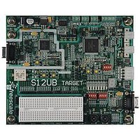
LFEBS12UB
Description
KIT STUDENT LEARNING S12 DG128
Manufacturer
Freescale Semiconductor
Specifications of LFEBS12UB
Architecture
8/16-bit
Code Gen Tools Included
Code Warrior
Silicon Manufacturer
Freescale
Core Architecture
S12
Core Sub-architecture
S12
Silicon Core Number
MC9S12
Silicon Family Name
S12D
Kit Contents
HCS12 DG128 Learning Kit
Rohs Compliant
Yes
Lead Free Status / RoHS Status
Lead free / RoHS Compliant


During power sequencing V
V
V
A.6
This section summarizes the electrical characteristics of the various startup scenarios for oscillator and
phase-locked loop (PLL).
A.6.1
Table A-23
startup behavior can be found in the Clock and Reset Generator (CRG) block description
1
2
A.6.1.1
The release level V
if the device is powered externally. After releasing the POR reset the oscillator and the clock quality check
are started. If after a time t
clock. The fastest startup time possible is given by n
Freescale Semiconductor
Conditions are shown in
Num C
DDR
RH
This is the time between RESET deassertion and start of CPU code execution.
Including voltage regulator startup; V
1
2
3
4
V
V
V
power up must follow V
DDA
DDR,
DDX
and V
D Reset input pulse width, minimum input time
D Startup from reset
D Wait recovery startup time
D Fast wakeup from STOP
V
Reset, Oscillator and PLL
summarizes several startup characteristics explained in this section. Detailed description of the
Startup
DDX
POR
must be powered up together adhering to the operating conditions differential.
PORR
Table
and the assert level V
CQOUT
A-4unless otherwise noted
Figure A-4. MC9S12XE-Family Power Sequencing
DDA
DDA
2
Rating
MC9S12XE-Family Reference Manual Rev. 1.23
DD
can be powered up before V
no valid oscillation is detected, the MCU will start using the internal self
to avoid current injection.
Table A-23. Startup Characteristics
/V
DDF
>= 0
filter capacitors 220 nF, V
PORA
are derived from the V
uposc
.
Symbol
PW
t
t
WRS
t
RST
DDR
fws
DD35
RSTL
, V
= 5 V, T= 25°C
DDX
Min
192
—
—
2
.
DD
Appendix A Electrical Characteristics
supply. They are also valid
Typ
50
—
—
—
4000
Max
100
14
—
1
t
Unit
n
t
t
µs
osc
cyc
bus
1237
Related parts for LFEBS12UB
Image
Part Number
Description
Manufacturer
Datasheet
Request
R

Part Number:
Description:
Manufacturer:
Freescale Semiconductor, Inc
Datasheet:
Part Number:
Description:
Manufacturer:
Freescale Semiconductor, Inc
Datasheet:
Part Number:
Description:
Manufacturer:
Freescale Semiconductor, Inc
Datasheet:
Part Number:
Description:
Manufacturer:
Freescale Semiconductor, Inc
Datasheet:
Part Number:
Description:
Manufacturer:
Freescale Semiconductor, Inc
Datasheet:
Part Number:
Description:
Manufacturer:
Freescale Semiconductor, Inc
Datasheet:
Part Number:
Description:
Manufacturer:
Freescale Semiconductor, Inc
Datasheet:
Part Number:
Description:
Manufacturer:
Freescale Semiconductor, Inc
Datasheet:
Part Number:
Description:
Manufacturer:
Freescale Semiconductor, Inc
Datasheet:
Part Number:
Description:
Manufacturer:
Freescale Semiconductor, Inc
Datasheet:
Part Number:
Description:
Manufacturer:
Freescale Semiconductor, Inc
Datasheet:
Part Number:
Description:
Manufacturer:
Freescale Semiconductor, Inc
Datasheet:
Part Number:
Description:
Manufacturer:
Freescale Semiconductor, Inc
Datasheet:
Part Number:
Description:
Manufacturer:
Freescale Semiconductor, Inc
Datasheet:
Part Number:
Description:
Manufacturer:
Freescale Semiconductor, Inc
Datasheet: