LFEBS12UB Freescale Semiconductor, LFEBS12UB Datasheet - Page 293
LFEBS12UB
Manufacturer Part Number
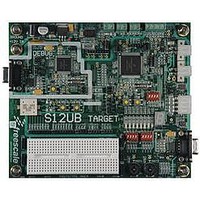
LFEBS12UB
Description
KIT STUDENT LEARNING S12 DG128
Manufacturer
Freescale Semiconductor
Specifications of LFEBS12UB
Architecture
8/16-bit
Code Gen Tools Included
Code Warrior
Silicon Manufacturer
Freescale
Core Architecture
S12
Core Sub-architecture
S12
Silicon Core Number
MC9S12
Silicon Family Name
S12D
Kit Contents
HCS12 DG128 Learning Kit
Rohs Compliant
Yes
Lead Free Status / RoHS Status
Lead free / RoHS Compliant


1. If enabled, ACK will occur when data is ready for transmission for all BDM READ commands and will occur after the write is
2. When the firmware command READ_NEXT or WRITE_NEXT is used to access the BDM address space the BDM resources
3. System stop disables the ACK function and ignored commands will not have an ACK-pulse (e.g., CPU in stop or wait mode).
7.4.5
Hardware and firmware BDM commands start with an 8-bit opcode followed by a 16-bit address and/or a
16-bit data word depending on the command. All the read commands return 16 bits of data despite the byte
or word implication in the command name.
Freescale Semiconductor
READ_NEXT
READ_PC
READ_D
READ_X
READ_Y
READ_SP
WRITE_NEXT
WRITE_PC
WRITE_D
WRITE_X
WRITE_Y
WRITE_SP
GO
GO_UNTIL
TRACE1
TAGGO -> GO
Because of an order from the United States International Trade Commission, BGA-packaged product lines and partnumbers
complete for all BDM WRITE commands.
are accessed rather than user code. Writing BDM firmware is not possible.
The GO_UNTIL command will not get an Acknowledge if CPU executes the wait or stop instruction before the “UNTIL”
condition (BDM active again) is reached (see
indicated here currently are not available from Freescale for import or sale in the United States prior to September 2010
Command
(3)
(2)
BDM Command Structure
(1)
8-bit reads return 16-bits of data, of which, only one byte will contain valid
data. If reading an even address, the valid data will appear in the MSB. If
reading an odd address, the valid data will appear in the LSB.
16-bit misaligned reads and writes are generally not allowed. If attempted
by BDM hardware command, the BDM will ignore the least significant bit
of the address and will assume an even address from the remaining bits.
Opcode
(hex)
0C
62
63
64
65
66
67
42
43
44
45
46
47
08
10
18
16-bit data out Increment X index register by 2 (X = X + 2), then read word X points to.
16-bit data out Read program counter.
16-bit data out Read D accumulator.
16-bit data out Read X index register.
16-bit data out Read Y index register.
16-bit data out Read stack pointer.
16-bit data in
16-bit data in
16-bit data in
16-bit data in
16-bit data in
16-bit data in
none
none
none
none
Data
MC9S12XE-Family Reference Manual Rev. 1.23
Table 7-7. Firmware Commands
Section 7.4.7, “Serial Interface Hardware Handshake Protocol”
Increment X index register by 2 (X = X + 2), then write word to location
pointed to by X.
Write program counter.
Write D accumulator.
Write X index register.
Write Y index register.
Write stack pointer.
Go to user program. If enabled, ACK will occur when leaving active
background mode.
Go to user program. If enabled, ACK will occur upon returning to active
background mode.
Execute one user instruction then return to active BDM. If enabled,
ACK will occur upon returning to active background mode.
(Previous enable tagging and go to user program.)
This command will be deprecated and should not be used anymore.
Opcode will be executed as a GO command.
Chapter 7 Background Debug Module (S12XBDMV2)
Description
last Note).
293
Related parts for LFEBS12UB
Image
Part Number
Description
Manufacturer
Datasheet
Request
R

Part Number:
Description:
Manufacturer:
Freescale Semiconductor, Inc
Datasheet:
Part Number:
Description:
Manufacturer:
Freescale Semiconductor, Inc
Datasheet:
Part Number:
Description:
Manufacturer:
Freescale Semiconductor, Inc
Datasheet:
Part Number:
Description:
Manufacturer:
Freescale Semiconductor, Inc
Datasheet:
Part Number:
Description:
Manufacturer:
Freescale Semiconductor, Inc
Datasheet:
Part Number:
Description:
Manufacturer:
Freescale Semiconductor, Inc
Datasheet:
Part Number:
Description:
Manufacturer:
Freescale Semiconductor, Inc
Datasheet:
Part Number:
Description:
Manufacturer:
Freescale Semiconductor, Inc
Datasheet:
Part Number:
Description:
Manufacturer:
Freescale Semiconductor, Inc
Datasheet:
Part Number:
Description:
Manufacturer:
Freescale Semiconductor, Inc
Datasheet:
Part Number:
Description:
Manufacturer:
Freescale Semiconductor, Inc
Datasheet:
Part Number:
Description:
Manufacturer:
Freescale Semiconductor, Inc
Datasheet:
Part Number:
Description:
Manufacturer:
Freescale Semiconductor, Inc
Datasheet:
Part Number:
Description:
Manufacturer:
Freescale Semiconductor, Inc
Datasheet:
Part Number:
Description:
Manufacturer:
Freescale Semiconductor, Inc
Datasheet: