LFEBS12UB Freescale Semiconductor, LFEBS12UB Datasheet - Page 275
LFEBS12UB
Manufacturer Part Number
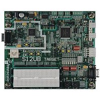
LFEBS12UB
Description
KIT STUDENT LEARNING S12 DG128
Manufacturer
Freescale Semiconductor
Specifications of LFEBS12UB
Architecture
8/16-bit
Code Gen Tools Included
Code Warrior
Silicon Manufacturer
Freescale
Core Architecture
S12
Core Sub-architecture
S12
Silicon Core Number
MC9S12
Silicon Family Name
S12D
Kit Contents
HCS12 DG128 Learning Kit
Rohs Compliant
Yes
Lead Free Status / RoHS Status
Lead free / RoHS Compliant


6.4
The XINT module processes all exception requests to be serviced by the CPU module. These exceptions
include interrupt vector requests and reset vector requests. Each of these exception types and their overall
priority level is discussed in the subsections below.
Freescale Semiconductor
PRIOLVL[2:0]
Because of an order from the United States International Trade Commission, BGA-packaged product lines and partnumbers
indicated here currently are not available from Freescale for import or sale in the United States prior to September 2010
RQST
Field
2–0
7
Functional Description
Priority
XGATE Request Enable — This bit determines if the associated interrupt request is handled by the CPU or by
the XGATE module.
0 Interrupt request is handled by the CPU
1 Interrupt request is handled by the XGATE module
Note: The IRQ interrupt cannot be handled by the XGATE module. For this reason, the configuration register
Note: If the XGATE module is not available on the device, writing a 1 to the location of the RQST bit in this
Interrupt Request Priority Level Bits — The PRIOLVL[2:0] bits configure the interrupt request priority level of
the associated interrupt request. Out of reset all interrupt requests are enabled at the lowest active level (“1”)
to provide backwards compatibility with previous S12 interrupt controllers. Please also refer to
available interrupt request priority levels.
Note: Write accesses to configuration data registers of unused interrupt channels will be ignored and read
Note: When vectors (vector base + 0x00F0–0x00FE) are selected by writing 0xF0 to INT_CFADDR, writes to
Note: When vectors (vector base + 0x0010–0x001E) are selected by writing 0x10 to INT_CFADDR, writes to
Note: Write accesses to the configuration register for the spurious interrupt vector request
high
low
for vector (vector base + 0x00F2) = IRQ vector address) does not contain a RQST bit. Writing a 1 to the
location of the RQST bit in this register will be ignored and a read access will return 0.
register will be ignored and a read access will return 0.
accesses will return all 0. For information about what interrupt channels are used in a specific MCU,
please refer to the Device Reference Manual of that MCU.
INT_CFDATA2–7 (0x00F4–0x00FE) will be ignored and read accesses will return all 0s. The
corresponding vectors do not have configuration data registers associated with them.
INT_CFDATA1–INT_CFDATA4 (0x0012–0x0018) will be ignored and read accesses will return all 0s. The
corresponding vectors do not have configuration data registers associated with them.
(vector base + 0x0010) will be ignored and read accesses will return 0x07 (request is handled by the
CPU, PRIOLVL = 7).
PRIOLVL2
0
0
0
0
1
1
1
1
Table 6-8. INT_CFDATA0–7 Field Descriptions
MC9S12XE-Family Reference Manual Rev. 1.23
Table 6-9. Interrupt Priority Levels
PRIOLVL1
0
0
1
1
0
0
1
1
PRIOLVL0
Description
0
1
0
1
0
1
0
1
Interrupt request is disabled
Priority level 1
Priority level 2
Priority level 3
Priority level 4
Priority level 5
Priority level 6
Priority level 7
Meaning
Chapter 6 Interrupt (S12XINTV2)
Table 6-9
for
275
Related parts for LFEBS12UB
Image
Part Number
Description
Manufacturer
Datasheet
Request
R

Part Number:
Description:
Manufacturer:
Freescale Semiconductor, Inc
Datasheet:
Part Number:
Description:
Manufacturer:
Freescale Semiconductor, Inc
Datasheet:
Part Number:
Description:
Manufacturer:
Freescale Semiconductor, Inc
Datasheet:
Part Number:
Description:
Manufacturer:
Freescale Semiconductor, Inc
Datasheet:
Part Number:
Description:
Manufacturer:
Freescale Semiconductor, Inc
Datasheet:
Part Number:
Description:
Manufacturer:
Freescale Semiconductor, Inc
Datasheet:
Part Number:
Description:
Manufacturer:
Freescale Semiconductor, Inc
Datasheet:
Part Number:
Description:
Manufacturer:
Freescale Semiconductor, Inc
Datasheet:
Part Number:
Description:
Manufacturer:
Freescale Semiconductor, Inc
Datasheet:
Part Number:
Description:
Manufacturer:
Freescale Semiconductor, Inc
Datasheet:
Part Number:
Description:
Manufacturer:
Freescale Semiconductor, Inc
Datasheet:
Part Number:
Description:
Manufacturer:
Freescale Semiconductor, Inc
Datasheet:
Part Number:
Description:
Manufacturer:
Freescale Semiconductor, Inc
Datasheet:
Part Number:
Description:
Manufacturer:
Freescale Semiconductor, Inc
Datasheet:
Part Number:
Description:
Manufacturer:
Freescale Semiconductor, Inc
Datasheet: