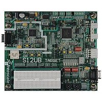
LFEBS12UB Freescale Semiconductor, LFEBS12UB Datasheet - Page 784

LFEBS12UB
Manufacturer Part Number
LFEBS12UB
Description
KIT STUDENT LEARNING S12 DG128
Manufacturer
Freescale Semiconductor
Specifications of LFEBS12UB
Architecture
8/16-bit
Code Gen Tools Included
Code Warrior
Silicon Manufacturer
Freescale
Core Architecture
S12
Core Sub-architecture
S12
Silicon Core Number
MC9S12
Silicon Family Name
S12D
Kit Contents
HCS12 DG128 Learning Kit
Rohs Compliant
Yes
Lead Free Status / RoHS Status
Lead free / RoHS Compliant
- Current page: 784 of 1328
- Download datasheet (9Mb)
Chapter 21 Serial Peripheral Interface (S12SPIV5)
When all bits are clear (the default condition), the SPI module clock is divided by 2. When the selection
bits (SPR2–SPR0) are 001 and the preselection bits (SPPR2–SPPR0) are 000, the module clock divisor
becomes 4. When the selection bits are 010, the module clock divisor becomes 8, etc.
When the preselection bits are 001, the divisor determined by the selection bits is multiplied by 2. When
the preselection bits are 010, the divisor is multiplied by 3, etc. See
for all bit conditions, based on a 25 MHz bus clock. The two sets of selects allows the clock to be divided
by a non-power of two to achieve other baud rates such as divide by 6, divide by 10, etc.
The baud rate generator is activated only when the SPI is in master mode and a serial transfer is taking
place. In the other cases, the divider is disabled to decrease I
21.4.5
21.4.5.1
The SS output feature automatically drives the SS pin low during transmission to select external devices
and drives it high during idle to deselect external devices. When SS output is selected, the SS output pin
is connected to the SS input pin of the external device.
The SS output is available only in master mode during normal SPI operation by asserting SSOE and
MODFEN bit as shown in
The mode fault feature is disabled while SS output is enabled.
21.4.5.2
The bidirectional mode is selected when the SPC0 bit is set in SPI control register 2 (see
this mode, the SPI uses only one serial data pin for the interface with external device(s). The MSTR bit
decides which pin to use. The MOSI pin becomes the serial data I/O (MOMI) pin for the master mode, and
the MISO pin becomes serial data I/O (SISO) pin for the slave mode. The MISO pin in master mode and
MOSI pin in slave mode are not used by the SPI.
784
Because of an order from the United States International Trade Commission, BGA-packaged product lines and partnumbers
indicated here currently are not available from Freescale for import or sale in the United States prior to September 2010
Special Features
SS Output
Bidirectional Mode (MOMI or SISO)
For maximum allowed baud rates, please refer to the SPI Electrical
Specification in the Electricals chapter of this data sheet.
Care must be taken when using the SS output feature in a multimaster
system because the mode fault feature is not available for detecting system
errors between masters.
Table
MC9S12XE-Family Reference Manual , Rev. 1.23
21-3.
NOTE
NOTE
DD
current.
Table 21-7
for baud rate calculations
Freescale Semiconductor
Table
21-11). In
Related parts for LFEBS12UB
Image
Part Number
Description
Manufacturer
Datasheet
Request
R
Part Number:
Description:
Manufacturer:
Freescale Semiconductor, Inc
Datasheet:
Part Number:
Description:
Manufacturer:
Freescale Semiconductor, Inc
Datasheet:
Part Number:
Description:
Manufacturer:
Freescale Semiconductor, Inc
Datasheet:
Part Number:
Description:
Manufacturer:
Freescale Semiconductor, Inc
Datasheet:
Part Number:
Description:
Manufacturer:
Freescale Semiconductor, Inc
Datasheet:
Part Number:
Description:
Manufacturer:
Freescale Semiconductor, Inc
Datasheet:
Part Number:
Description:
Manufacturer:
Freescale Semiconductor, Inc
Datasheet:
Part Number:
Description:
Manufacturer:
Freescale Semiconductor, Inc
Datasheet:
Part Number:
Description:
Manufacturer:
Freescale Semiconductor, Inc
Datasheet:
Part Number:
Description:
Manufacturer:
Freescale Semiconductor, Inc
Datasheet:
Part Number:
Description:
Manufacturer:
Freescale Semiconductor, Inc
Datasheet:
Part Number:
Description:
Manufacturer:
Freescale Semiconductor, Inc
Datasheet:
Part Number:
Description:
Manufacturer:
Freescale Semiconductor, Inc
Datasheet:
Part Number:
Description:
Manufacturer:
Freescale Semiconductor, Inc
Datasheet:
Part Number:
Description:
Manufacturer:
Freescale Semiconductor, Inc
Datasheet:


