LFEBS12UB Freescale Semiconductor, LFEBS12UB Datasheet - Page 525
LFEBS12UB
Manufacturer Part Number
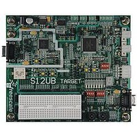
LFEBS12UB
Description
KIT STUDENT LEARNING S12 DG128
Manufacturer
Freescale Semiconductor
Specifications of LFEBS12UB
Architecture
8/16-bit
Code Gen Tools Included
Code Warrior
Silicon Manufacturer
Freescale
Core Architecture
S12
Core Sub-architecture
S12
Silicon Core Number
MC9S12
Silicon Family Name
S12D
Kit Contents
HCS12 DG128 Learning Kit
Rohs Compliant
Yes
Lead Free Status / RoHS Status
Lead free / RoHS Compliant


13.4
The ADC12B16C is structured into an analog sub-block and a digital sub-block.
13.4.1
The analog sub-block contains all analog electronics required to perform a single conversion. Separate
power supplies V
13.4.1.1
The Sample and Hold (S/H) Machine accepts analog signals from the external world and stores them as
capacitor charge on a storage node.
During the sample process the analog input connects directly to the storage node.
The input analog signals are unipolar and must fall within the potential range of V
During the hold process the analog input is disconnected from the storage node.
13.4.1.2
The analog input multiplexer connects one of the 16 external analog input channels to the sample and hold
machine.
13.4.1.3
The A/D Machine performs analog to digital conversions. The resolution is program selectable at either 8
or 10 or 12 bits. The A/D machine uses a successive approximation architecture. It functions by comparing
the stored analog sample potential with a series of digitally generated analog potentials. By following a
binary search algorithm, the A/D machine locates the approximating potential that is nearest to the
sampled potential.
When not converting the A/D machine is automatically powered down.
Freescale Semiconductor
Because of an order from the United States International Trade Commission, BGA-packaged product lines and partnumbers
indicated here currently are not available from Freescale for import or sale in the United States prior to September 2010
Functional Description
Analog Sub-Block
Sample and Hold Machine
Analog Input Multiplexer
Analog-to-Digital (A/D) Machine
DDA
and V
Table 13-22. Conversion result mapping to ATDDRn
SSA
resolution
MC9S12XE-Family Reference Manual Rev. 1.23
10-bit data
10-bit data
12-bit data
8-bit data
8-bit data
allow to isolate noise of other MCU circuitry from the analog sub-block.
A/D
0
1
0
1
X
DJM
conversion result mapping to
Bit[11:4] = result, Bit[3:0]=0000
Bit[7:0] = result, Bit[11:8]=0000
Bit[11:2] = result, Bit[1:0]=00
Bit[9:0] = result, Bit[11:10]=00
Bit[11:0] = result
ATDDRn
Chapter 13 Analog-to-Digital Converter (ADC12B16CV1)
SSA
to V
DDA
.
525
Related parts for LFEBS12UB
Image
Part Number
Description
Manufacturer
Datasheet
Request
R

Part Number:
Description:
Manufacturer:
Freescale Semiconductor, Inc
Datasheet:
Part Number:
Description:
Manufacturer:
Freescale Semiconductor, Inc
Datasheet:
Part Number:
Description:
Manufacturer:
Freescale Semiconductor, Inc
Datasheet:
Part Number:
Description:
Manufacturer:
Freescale Semiconductor, Inc
Datasheet:
Part Number:
Description:
Manufacturer:
Freescale Semiconductor, Inc
Datasheet:
Part Number:
Description:
Manufacturer:
Freescale Semiconductor, Inc
Datasheet:
Part Number:
Description:
Manufacturer:
Freescale Semiconductor, Inc
Datasheet:
Part Number:
Description:
Manufacturer:
Freescale Semiconductor, Inc
Datasheet:
Part Number:
Description:
Manufacturer:
Freescale Semiconductor, Inc
Datasheet:
Part Number:
Description:
Manufacturer:
Freescale Semiconductor, Inc
Datasheet:
Part Number:
Description:
Manufacturer:
Freescale Semiconductor, Inc
Datasheet:
Part Number:
Description:
Manufacturer:
Freescale Semiconductor, Inc
Datasheet:
Part Number:
Description:
Manufacturer:
Freescale Semiconductor, Inc
Datasheet:
Part Number:
Description:
Manufacturer:
Freescale Semiconductor, Inc
Datasheet:
Part Number:
Description:
Manufacturer:
Freescale Semiconductor, Inc
Datasheet: