LFEBS12UB Freescale Semiconductor, LFEBS12UB Datasheet - Page 575
LFEBS12UB
Manufacturer Part Number
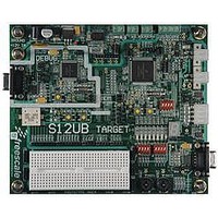
LFEBS12UB
Description
KIT STUDENT LEARNING S12 DG128
Manufacturer
Freescale Semiconductor
Specifications of LFEBS12UB
Architecture
8/16-bit
Code Gen Tools Included
Code Warrior
Silicon Manufacturer
Freescale
Core Architecture
S12
Core Sub-architecture
S12
Silicon Core Number
MC9S12
Silicon Family Name
S12D
Kit Contents
HCS12 DG128 Learning Kit
Rohs Compliant
Yes
Lead Free Status / RoHS Status
Lead free / RoHS Compliant


14.4.1
The enhanced capture timer has 8 input capture, output compare (IC/OC) channels, same as on the HC12
standard timer (timer channels TC0 to TC7). When channels are selected as input capture by selecting the
IOSx bit in TIOS register, they are called input capture (IC) channels.
Four IC channels (channels 7–4) are the same as on the standard timer with one capture register each that
memorizes the timer value captured by an action on the associated input pin.
Four other IC channels (channels 3–0), in addition to the capture register, also have one buffer each called
a holding register. This allows two different timer values to be saved without generating any interrupts.
Four 8-bit pulse accumulators are associated with the four buffered IC channels (channels 3–0). Each pulse
accumulator has a holding register to memorize their value by an action on its external input. Each pair of
pulse accumulators can be used as a 16-bit pulse accumulator.
The 16-bit modulus down-counter can control the transfer of the IC registers and the pulse accumulators
contents to the respective holding registers for a given period, every time the count reaches zero.
The modulus down-counter can also be used as a stand-alone time base with periodic interrupt capability.
14.4.1.1
The IC channels are composed of four standard IC registers and four buffered IC channels.
14.4.1.1.1
The main timer value is memorized in the IC register by a valid input pin transition. If the corresponding
NOVWx bit of the ICOVW register is cleared, with a new occurrence of a capture, the contents of IC
register are overwritten by the new value. If the corresponding NOVWx bit of the ICOVW register is set,
the capture register cannot be written unless it is empty. This will prevent the captured value from being
overwritten until it is read.
14.4.1.1.2
There are two modes of operations for the buffered IC channels:
Freescale Semiconductor
Because of an order from the United States International Trade Commission, BGA-packaged product lines and partnumbers
indicated here currently are not available from Freescale for import or sale in the United States prior to September 2010
•
•
1. IC latch mode (LATQ = 1)
An IC register is empty when it has been read or latched into the holding register.
A holding register is empty when it has been read.
The main timer value is memorized in the IC register by a valid input pin transition (see
67
The value of the buffered IC register is latched to its holding register by the modulus counter for a
given period when the count reaches zero, by a write 0x0000 to the modulus counter or by a write
to ICLAT in the MCCTL register.
If the corresponding NOVWx bit of the ICOVW register is cleared, with a new occurrence of a
capture, the contents of IC register are overwritten by the new value. In case of latching, the
contents of its holding register are overwritten.
and
Enhanced Capture Timer Modes of Operation
IC Channels
Figure
Non-Buffered IC Channels
Buffered IC Channels
14-68).
MC9S12XE-Family Reference Manual Rev. 1.23
Chapter 14 Enhanced Capture Timer (ECT16B8CV3)
Figure 14-
575
Related parts for LFEBS12UB
Image
Part Number
Description
Manufacturer
Datasheet
Request
R

Part Number:
Description:
Manufacturer:
Freescale Semiconductor, Inc
Datasheet:
Part Number:
Description:
Manufacturer:
Freescale Semiconductor, Inc
Datasheet:
Part Number:
Description:
Manufacturer:
Freescale Semiconductor, Inc
Datasheet:
Part Number:
Description:
Manufacturer:
Freescale Semiconductor, Inc
Datasheet:
Part Number:
Description:
Manufacturer:
Freescale Semiconductor, Inc
Datasheet:
Part Number:
Description:
Manufacturer:
Freescale Semiconductor, Inc
Datasheet:
Part Number:
Description:
Manufacturer:
Freescale Semiconductor, Inc
Datasheet:
Part Number:
Description:
Manufacturer:
Freescale Semiconductor, Inc
Datasheet:
Part Number:
Description:
Manufacturer:
Freescale Semiconductor, Inc
Datasheet:
Part Number:
Description:
Manufacturer:
Freescale Semiconductor, Inc
Datasheet:
Part Number:
Description:
Manufacturer:
Freescale Semiconductor, Inc
Datasheet:
Part Number:
Description:
Manufacturer:
Freescale Semiconductor, Inc
Datasheet:
Part Number:
Description:
Manufacturer:
Freescale Semiconductor, Inc
Datasheet:
Part Number:
Description:
Manufacturer:
Freescale Semiconductor, Inc
Datasheet:
Part Number:
Description:
Manufacturer:
Freescale Semiconductor, Inc
Datasheet: