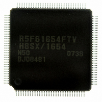
DF61654N50FTV Renesas Electronics America, DF61654N50FTV Datasheet - Page 47

DF61654N50FTV
Manufacturer Part Number
DF61654N50FTV
Description
IC H8SX/1654 MCU FLASH 120TQFP
Manufacturer
Renesas Electronics America
Series
H8® H8SX/1600r
Datasheet
1.DF61653N50FTV.pdf
(1020 pages)
Specifications of DF61654N50FTV
Core Processor
H8SX
Core Size
32-Bit
Speed
50MHz
Connectivity
I²C, IrDA, SCI, SmartCard, USB
Peripherals
DMA, PWM, WDT
Number Of I /o
75
Program Memory Size
512KB (512K x 8)
Program Memory Type
FLASH
Ram Size
40K x 8
Voltage - Supply (vcc/vdd)
3 V ~ 3.6 V
Data Converters
A/D 8x10b; D/A 2x8b
Oscillator Type
External
Operating Temperature
-20°C ~ 75°C
Package / Case
120-TQFP, 120-VQFP
For Use With
HS0005KCU11H - EMULATOR E10A-USB H8S(X),SH2(A)3DK1657 - DEV EVAL KIT FOR H8SX/1657
Lead Free Status / RoHS Status
Lead free / RoHS Compliant
Eeprom Size
-
Available stocks
Company
Part Number
Manufacturer
Quantity
Price
Company:
Part Number:
DF61654N50FTV
Manufacturer:
Renesas Electronics America
Quantity:
10 000
- Current page: 47 of 1020
- Download datasheet (6Mb)
Table 14.3
Table 14.4
Table 14.4
Table 14.5
Table 14.6
Table 14.7
Table 14.8
Table 14.9
Table 14.10
Table 14.11
Table 14.12
Table 14.13
Table 14.14
Table 14.15
Table 14.16
Table 14.17
Section 15 USB Function Module (USB)
Table 15.1
Table 15.2
Table 15.3
Table 15.4
Table 15.5
Table 15.6
Table 15.7
Table 15.8
Section 16 I2C Bus Interface2 (IIC2)
Table 16.1
Table 16.2
Table 16.3
Table 16.4
Section 17 A/D Converter
Table 17.1
Table 17.2
Table 17.3
Table 17.4
Table 17.5
Table 17.6
Relationships between N Setting in BRR and Bit Rate B..................................... 569
Examples of BRR Settings for Various Bit Rates (Asynchronous Mode) (1) ...... 570
Examples of BRR Settings for Various Bit Rates (Asynchronous Mode) (2) ...... 571
Maximum Bit Rate for Each Operating Frequency (Asynchronous Mode).......... 572
Maximum Bit Rate with External Clock Input (Asynchronous Mode) ................ 573
BRR Settings for Various Bit Rates (Clocked Synchronous Mode)..................... 574
Maximum Bit Rate with External Clock Input (Clocked Synchronous Mode) .... 574
BRR Settings for Various Bit Rates
(Smart Card Interface Mode, n = 0, S = 372) ....................................................... 575
Pin Configuration.................................................................................................. 640
Example of Limitations for Setting Values........................................................... 666
Example of Setting................................................................................................ 667
Relationship between TRNTREG0 Setting and Pin Output ................................. 669
Relationship between Pin Input and TRNTREG1 Monitoring Value................... 671
Interrupt Sources................................................................................................... 672
Command Decoding on Application Side............................................................. 691
Selection of Peripheral Clock (Pφ) when USB is Connected................................ 701
Pin configuration of the I
Transfer Rate ........................................................................................................ 708
Interrupt Requests ................................................................................................. 732
Time for Monitoring SCL..................................................................................... 733
Pin Configuration.................................................................................................. 737
Analog Input Channels and Corresponding ADDR Registers .............................. 738
A/D Conversion Characteristics (Single Mode).................................................... 746
A/D Conversion Characteristics (Scan Mode) ...................................................... 746
A/D Converter Interrupt Source............................................................................ 747
Analog Pin Specifications..................................................................................... 751
Maximum Bit Rate for Each Operating Frequency
(Smart Card Interface Mode, S = 372).............................................................. 575
Serial Transfer Formats (Asynchronous Mode)................................................ 587
SSR Status Flags and Receive Data Handling .................................................. 594
IrCKS2 to IrCKS0 Bit Settings......................................................................... 623
SCI Interrupt Sources (SCI_0, 1, 2, and 4) ....................................................... 624
SCI Interrupt Sources (SCI_5 and SCI_6) ........................................................ 625
SCI Interrupt Sources (SCI_0, 1, 2, and 4) ....................................................... 625
SCI Interrupt Sources (SCI_5 and SCI_6) ........................................................ 625
2
C bus interface2........................................................... 705
Rev.1.00 Sep. 08, 2005 Page xlv of xlviii
Related parts for DF61654N50FTV
Image
Part Number
Description
Manufacturer
Datasheet
Request
R

Part Number:
Description:
KIT STARTER FOR M16C/29
Manufacturer:
Renesas Electronics America
Datasheet:

Part Number:
Description:
KIT STARTER FOR R8C/2D
Manufacturer:
Renesas Electronics America
Datasheet:

Part Number:
Description:
R0K33062P STARTER KIT
Manufacturer:
Renesas Electronics America
Datasheet:

Part Number:
Description:
KIT STARTER FOR R8C/23 E8A
Manufacturer:
Renesas Electronics America
Datasheet:

Part Number:
Description:
KIT STARTER FOR R8C/25
Manufacturer:
Renesas Electronics America
Datasheet:

Part Number:
Description:
KIT STARTER H8S2456 SHARPE DSPLY
Manufacturer:
Renesas Electronics America
Datasheet:

Part Number:
Description:
KIT STARTER FOR R8C38C
Manufacturer:
Renesas Electronics America
Datasheet:

Part Number:
Description:
KIT STARTER FOR R8C35C
Manufacturer:
Renesas Electronics America
Datasheet:

Part Number:
Description:
KIT STARTER FOR R8CL3AC+LCD APPS
Manufacturer:
Renesas Electronics America
Datasheet:

Part Number:
Description:
KIT STARTER FOR RX610
Manufacturer:
Renesas Electronics America
Datasheet:

Part Number:
Description:
KIT STARTER FOR R32C/118
Manufacturer:
Renesas Electronics America
Datasheet:

Part Number:
Description:
KIT DEV RSK-R8C/26-29
Manufacturer:
Renesas Electronics America
Datasheet:

Part Number:
Description:
KIT STARTER FOR SH7124
Manufacturer:
Renesas Electronics America
Datasheet:

Part Number:
Description:
KIT STARTER FOR H8SX/1622
Manufacturer:
Renesas Electronics America
Datasheet:

Part Number:
Description:
KIT DEV FOR SH7203
Manufacturer:
Renesas Electronics America
Datasheet:


