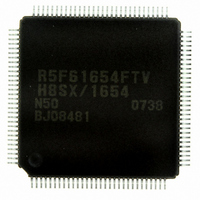
DF61654N50FTV Renesas Electronics America, DF61654N50FTV Datasheet - Page 39

DF61654N50FTV
Manufacturer Part Number
DF61654N50FTV
Description
IC H8SX/1654 MCU FLASH 120TQFP
Manufacturer
Renesas Electronics America
Series
H8® H8SX/1600r
Datasheet
1.DF61653N50FTV.pdf
(1020 pages)
Specifications of DF61654N50FTV
Core Processor
H8SX
Core Size
32-Bit
Speed
50MHz
Connectivity
I²C, IrDA, SCI, SmartCard, USB
Peripherals
DMA, PWM, WDT
Number Of I /o
75
Program Memory Size
512KB (512K x 8)
Program Memory Type
FLASH
Ram Size
40K x 8
Voltage - Supply (vcc/vdd)
3 V ~ 3.6 V
Data Converters
A/D 8x10b; D/A 2x8b
Oscillator Type
External
Operating Temperature
-20°C ~ 75°C
Package / Case
120-TQFP, 120-VQFP
For Use With
HS0005KCU11H - EMULATOR E10A-USB H8S(X),SH2(A)3DK1657 - DEV EVAL KIT FOR H8SX/1657
Lead Free Status / RoHS Status
Lead free / RoHS Compliant
Eeprom Size
-
Available stocks
Company
Part Number
Manufacturer
Quantity
Price
Company:
Part Number:
DF61654N50FTV
Manufacturer:
Renesas Electronics America
Quantity:
10 000
- Current page: 39 of 1020
- Download datasheet (6Mb)
Figure 20.10 USB Boot Mode State Transition Diagram ........................................................... 795
Figure 20.11 Programming/Erasing Flow................................................................................... 797
Figure 20.12 RAM Map when Programming/Erasing is Executed ............................................ 798
Figure 20.13 Programming Procedure in User Program Mode .................................................. 799
Figure 20.14 Erasing Procedure in User Program Mode ............................................................ 804
Figure 20.15 Repeating Procedure of Erasing, Programming,
Figure 20.16 Transitions to Error Protection State ..................................................................... 812
Figure 20.17 RAM Emulation Flow ........................................................................................... 813
Figure 20.18 Address Map of Overlaid RAM Area (H8SX/1653) ............................................. 814
Figure 20.19 Programming Tuned Data (H8SX/1653)............................................................... 815
Figure 20.20 Boot Program States .............................................................................................. 817
Figure 20.21 Bit-Rate-Adjustment Sequence ............................................................................. 818
Figure 20.22 Communication Protocol Format .......................................................................... 819
Figure 20.23 New Bit-Rate Selection Sequence......................................................................... 830
Figure 20.24 Programming Sequence......................................................................................... 833
Figure 20.25 Erasure Sequence .................................................................................................. 833
Section 21 Clock Pulse Generator
Figure 21.1 Block Diagram of Clock Pulse Generator ............................................................... 844
Figure 21.2 Connection of Crystal Resonator (Example)........................................................... 848
Figure 21.3 Crystal Resonator Equivalent Circuit ...................................................................... 848
Figure 21.4 External Clock Input (Examples) ............................................................................ 849
Figure 21.5 External Clock Input Timing................................................................................... 849
Figure 21.6 Clock Modification Timing..................................................................................... 851
Figure 21.7 Note on Board Design for Oscillation Circuit ......................................................... 852
Figure 21.8 Recommended External Circuitry for PLL Circuit ................................................. 852
Section 22 Power-Down Modes
Figure 22.1 Mode Transitions..................................................................................................... 855
Figure 22.2 Software Standby Mode Application Example ....................................................... 867
Figure 22.3 Hardware Standby Mode Timing ............................................................................ 868
Figure 22.4 Timing Sequence at Power-On................................................................................ 869
Figure 22.5 When Canceling Factor Interrupt is Generated
Figure 22.6 When Canceling Factor Interrupt is Generated
Figure 22.7 When Canceling Factor Interrupt is Generated
after SLEEP Instruction Execution .......................................................................... 872
before SLEEP Instruction Execution (Sleep Interrupt Disabled)............................. 872
before SLEEP Instruction Execution (Sleep Interrupt Enabled).............................. 873
and RAM Emulation in User Program Mode ....................................................... 806
Rev.1.00 Sep. 08, 2005 Page xxxvii of xlviii
Related parts for DF61654N50FTV
Image
Part Number
Description
Manufacturer
Datasheet
Request
R

Part Number:
Description:
KIT STARTER FOR M16C/29
Manufacturer:
Renesas Electronics America
Datasheet:

Part Number:
Description:
KIT STARTER FOR R8C/2D
Manufacturer:
Renesas Electronics America
Datasheet:

Part Number:
Description:
R0K33062P STARTER KIT
Manufacturer:
Renesas Electronics America
Datasheet:

Part Number:
Description:
KIT STARTER FOR R8C/23 E8A
Manufacturer:
Renesas Electronics America
Datasheet:

Part Number:
Description:
KIT STARTER FOR R8C/25
Manufacturer:
Renesas Electronics America
Datasheet:

Part Number:
Description:
KIT STARTER H8S2456 SHARPE DSPLY
Manufacturer:
Renesas Electronics America
Datasheet:

Part Number:
Description:
KIT STARTER FOR R8C38C
Manufacturer:
Renesas Electronics America
Datasheet:

Part Number:
Description:
KIT STARTER FOR R8C35C
Manufacturer:
Renesas Electronics America
Datasheet:

Part Number:
Description:
KIT STARTER FOR R8CL3AC+LCD APPS
Manufacturer:
Renesas Electronics America
Datasheet:

Part Number:
Description:
KIT STARTER FOR RX610
Manufacturer:
Renesas Electronics America
Datasheet:

Part Number:
Description:
KIT STARTER FOR R32C/118
Manufacturer:
Renesas Electronics America
Datasheet:

Part Number:
Description:
KIT DEV RSK-R8C/26-29
Manufacturer:
Renesas Electronics America
Datasheet:

Part Number:
Description:
KIT STARTER FOR SH7124
Manufacturer:
Renesas Electronics America
Datasheet:

Part Number:
Description:
KIT STARTER FOR H8SX/1622
Manufacturer:
Renesas Electronics America
Datasheet:

Part Number:
Description:
KIT DEV FOR SH7203
Manufacturer:
Renesas Electronics America
Datasheet:


