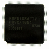
DF61654N50FTV Renesas Electronics America, DF61654N50FTV Datasheet - Page 1011

DF61654N50FTV
Manufacturer Part Number
DF61654N50FTV
Description
IC H8SX/1654 MCU FLASH 120TQFP
Manufacturer
Renesas Electronics America
Series
H8® H8SX/1600r
Datasheet
1.DF61653N50FTV.pdf
(1020 pages)
Specifications of DF61654N50FTV
Core Processor
H8SX
Core Size
32-Bit
Speed
50MHz
Connectivity
I²C, IrDA, SCI, SmartCard, USB
Peripherals
DMA, PWM, WDT
Number Of I /o
75
Program Memory Size
512KB (512K x 8)
Program Memory Type
FLASH
Ram Size
40K x 8
Voltage - Supply (vcc/vdd)
3 V ~ 3.6 V
Data Converters
A/D 8x10b; D/A 2x8b
Oscillator Type
External
Operating Temperature
-20°C ~ 75°C
Package / Case
120-TQFP, 120-VQFP
For Use With
HS0005KCU11H - EMULATOR E10A-USB H8S(X),SH2(A)3DK1657 - DEV EVAL KIT FOR H8SX/1657
Lead Free Status / RoHS Status
Lead free / RoHS Compliant
Eeprom Size
-
Available stocks
Company
Part Number
Manufacturer
Quantity
Price
Company:
Part Number:
DF61654N50FTV
Manufacturer:
Renesas Electronics America
Quantity:
10 000
- Current page: 1011 of 1020
- Download datasheet (6Mb)
Numerics
0-output and 1-output ............................. 438
16-bit access space.................................. 170
16-bit counter mode................................ 523
16-bit timer pulse unit (TPU) ................. 395
8-bit access space.................................... 169
8-bit timers (TMR) ................................. 501
A
A/D conversion accuracy........................ 747
A/D converter ......................................... 735
Absolute accuracy................................... 747
Acknowledge .......................................... 718
Address error ............................................ 80
Address map ............................................. 69
Address modes........................................ 255
Address/data multiplexed I/O
interface .......................................... 163, 198
All-module-clock-stop mode .......... 854, 870
Area 0 ..................................................... 164
Area 1 ..................................................... 165
Area 2 ..................................................... 165
Area 3 ..................................................... 166
Area 4 ..................................................... 166
Area 5 ..................................................... 167
Area 6 ..................................................... 168
Area 7 ..................................................... 168
Area division........................................... 158
Asynchronous mode ............................... 586
AT-cut parallel-resonance type............... 848
Available output signal and settings
in each port ............................................. 378
Average transfer rate generator............... 544
Index
B
Bφ clock output control........................... 874
Basic bus interface .......................... 162, 172
Big endian ............................................... 161
Bit rate..................................................... 569
Bit synchronous circuit ........................... 732
Block diagram............................................. 2
Block structure ........................................ 765
Block transfer mode ........................ 261, 329
Boot mode....................................... 763, 789
Bulk-in transfer ....................................... 688
Bulk-out transfer ..................................... 687
Burst access mode................................... 267
Burst ROM interface....................... 162, 193
Bus access modes.................................... 266
Bus arbitration......................................... 224
Bus configuration.................................... 150
Bus controller (BSC)............................... 125
Bus cycle division ................................... 323
Bus width ................................................ 161
Byte control SRAM interface ......... 162, 185
C
Cascaded connection............................... 523
Cascaded operation ................................. 447
Chain transfer.......................................... 330
Chip select signals................................... 159
Clock pulse generator ............................. 843
Clock synchronization cycle (Tsy).......... 152
Clocked synchronous mode .................... 603
Communications protocol ....................... 818
Compare match A ................................... 521
Compare match B ................................... 522
Compare match count mode ................... 524
Compare match signal............................. 521
Control transfer ....................................... 681
Rev.1.00 Sep. 08, 2005 Page 961 of 966
REJ09B0219-0100
Related parts for DF61654N50FTV
Image
Part Number
Description
Manufacturer
Datasheet
Request
R

Part Number:
Description:
KIT STARTER FOR M16C/29
Manufacturer:
Renesas Electronics America
Datasheet:

Part Number:
Description:
KIT STARTER FOR R8C/2D
Manufacturer:
Renesas Electronics America
Datasheet:

Part Number:
Description:
R0K33062P STARTER KIT
Manufacturer:
Renesas Electronics America
Datasheet:

Part Number:
Description:
KIT STARTER FOR R8C/23 E8A
Manufacturer:
Renesas Electronics America
Datasheet:

Part Number:
Description:
KIT STARTER FOR R8C/25
Manufacturer:
Renesas Electronics America
Datasheet:

Part Number:
Description:
KIT STARTER H8S2456 SHARPE DSPLY
Manufacturer:
Renesas Electronics America
Datasheet:

Part Number:
Description:
KIT STARTER FOR R8C38C
Manufacturer:
Renesas Electronics America
Datasheet:

Part Number:
Description:
KIT STARTER FOR R8C35C
Manufacturer:
Renesas Electronics America
Datasheet:

Part Number:
Description:
KIT STARTER FOR R8CL3AC+LCD APPS
Manufacturer:
Renesas Electronics America
Datasheet:

Part Number:
Description:
KIT STARTER FOR RX610
Manufacturer:
Renesas Electronics America
Datasheet:

Part Number:
Description:
KIT STARTER FOR R32C/118
Manufacturer:
Renesas Electronics America
Datasheet:

Part Number:
Description:
KIT DEV RSK-R8C/26-29
Manufacturer:
Renesas Electronics America
Datasheet:

Part Number:
Description:
KIT STARTER FOR SH7124
Manufacturer:
Renesas Electronics America
Datasheet:

Part Number:
Description:
KIT STARTER FOR H8SX/1622
Manufacturer:
Renesas Electronics America
Datasheet:

Part Number:
Description:
KIT DEV FOR SH7203
Manufacturer:
Renesas Electronics America
Datasheet:


