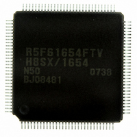
DF61654N50FTV Renesas Electronics America, DF61654N50FTV Datasheet - Page 38

DF61654N50FTV
Manufacturer Part Number
DF61654N50FTV
Description
IC H8SX/1654 MCU FLASH 120TQFP
Manufacturer
Renesas Electronics America
Series
H8® H8SX/1600r
Datasheet
1.DF61653N50FTV.pdf
(1020 pages)
Specifications of DF61654N50FTV
Core Processor
H8SX
Core Size
32-Bit
Speed
50MHz
Connectivity
I²C, IrDA, SCI, SmartCard, USB
Peripherals
DMA, PWM, WDT
Number Of I /o
75
Program Memory Size
512KB (512K x 8)
Program Memory Type
FLASH
Ram Size
40K x 8
Voltage - Supply (vcc/vdd)
3 V ~ 3.6 V
Data Converters
A/D 8x10b; D/A 2x8b
Oscillator Type
External
Operating Temperature
-20°C ~ 75°C
Package / Case
120-TQFP, 120-VQFP
For Use With
HS0005KCU11H - EMULATOR E10A-USB H8S(X),SH2(A)3DK1657 - DEV EVAL KIT FOR H8SX/1657
Lead Free Status / RoHS Status
Lead free / RoHS Compliant
Eeprom Size
-
Available stocks
Company
Part Number
Manufacturer
Quantity
Price
Company:
Part Number:
DF61654N50FTV
Manufacturer:
Renesas Electronics America
Quantity:
10 000
- Current page: 38 of 1020
- Download datasheet (6Mb)
Figure 16.5 Master Transmit Mode Operation Timing 1............................................................ 720
Figure 16.6 Master Transmit Mode Operation Timing 2............................................................ 720
Figure 16.7 Master Receive Mode Operation Timing 1 ............................................................. 722
Figure 16.8 Master Receive Mode Operation Timing 2 ............................................................. 723
Figure 16.9 Slave Transmit Mode Operation Timing 1.............................................................. 724
Figure 16.10 Slave Transmit Mode Operation Timing 2............................................................ 725
Figure 16.11 Slave Receive Mode Operation Timing 1 ............................................................. 726
Figure 16.12 Slave Receive Mode Operation Timing 2 ............................................................. 727
Figure 16.13 Block Diagram of Noise Canceler......................................................................... 727
Figure 16.14 Sample Flowchart of Master Transmit Mode........................................................ 728
Figure 16.15 Sample Flowchart for Master Receive Mode ........................................................ 729
Figure 16.16 Sample Flowchart for Slave Transmit Mode......................................................... 730
Figure 16.17 Sample Flowchart for Slave Receive Mode .......................................................... 731
Figure 16.18 Timing of the Bit Synchronous Circuit ................................................................. 733
Section 17 A/D Converter
Figure 17.1 Block Diagram of A/D Converter ........................................................................... 736
Figure 17.2 Example of A/D Converter Operation (Single Mode, Channel 1 Selected) ............ 743
Figure 17.3 Example of A/D Conversion
(Scan Mode, Three Channels (AN0 to AN2) Selected) .......................................... 744
Figure 17.4 A/D Conversion Timing.......................................................................................... 745
Figure 17.5 External Trigger Input Timing ................................................................................ 746
Figure 17.6 A/D Conversion Accuracy Definitions ................................................................... 748
Figure 17.7 A/D Conversion Accuracy Definitions ................................................................... 748
Figure 17.8 Example of Analog Input Circuit ............................................................................ 749
Figure 17.9 Example of Analog Input Protection Circuit........................................................... 751
Figure 17.10 Analog Input Pin Equivalent Circuit ..................................................................... 751
Section 18 D/A Converter
Figure 18.1 Block Diagram of D/A Converter ........................................................................... 753
Figure 18.2 Example of D/A Converter Operation..................................................................... 757
Section 20 Flash Memory (0.18-mm F-ZTAT Version)
Figure 20.1 Block Diagram of Flash Memory............................................................................ 762
Figure 20.2 Mode Transition of Flash Memory.......................................................................... 763
Figure 20.3 Block Structure of User MAT ................................................................................. 765
Figure 20.4 Block Structure of User MAT ................................................................................. 766
Figure 20.5 Procedure for Creating Procedure Program............................................................. 767
Figure 20.6 System Configuration in SCI Boot Mode................................................................ 789
Figure 20.7 Automatic-Bit-Rate Adjustment Operation............................................................. 790
Figure 20.8 SCI Boot Mode State Transition Diagram .............................................................. 791
Figure 20.9 System Configuration in USB Boot Mode .............................................................. 793
Rev.1.00 Sep. 08, 2005 Page xxxvi of xlviii
Related parts for DF61654N50FTV
Image
Part Number
Description
Manufacturer
Datasheet
Request
R

Part Number:
Description:
KIT STARTER FOR M16C/29
Manufacturer:
Renesas Electronics America
Datasheet:

Part Number:
Description:
KIT STARTER FOR R8C/2D
Manufacturer:
Renesas Electronics America
Datasheet:

Part Number:
Description:
R0K33062P STARTER KIT
Manufacturer:
Renesas Electronics America
Datasheet:

Part Number:
Description:
KIT STARTER FOR R8C/23 E8A
Manufacturer:
Renesas Electronics America
Datasheet:

Part Number:
Description:
KIT STARTER FOR R8C/25
Manufacturer:
Renesas Electronics America
Datasheet:

Part Number:
Description:
KIT STARTER H8S2456 SHARPE DSPLY
Manufacturer:
Renesas Electronics America
Datasheet:

Part Number:
Description:
KIT STARTER FOR R8C38C
Manufacturer:
Renesas Electronics America
Datasheet:

Part Number:
Description:
KIT STARTER FOR R8C35C
Manufacturer:
Renesas Electronics America
Datasheet:

Part Number:
Description:
KIT STARTER FOR R8CL3AC+LCD APPS
Manufacturer:
Renesas Electronics America
Datasheet:

Part Number:
Description:
KIT STARTER FOR RX610
Manufacturer:
Renesas Electronics America
Datasheet:

Part Number:
Description:
KIT STARTER FOR R32C/118
Manufacturer:
Renesas Electronics America
Datasheet:

Part Number:
Description:
KIT DEV RSK-R8C/26-29
Manufacturer:
Renesas Electronics America
Datasheet:

Part Number:
Description:
KIT STARTER FOR SH7124
Manufacturer:
Renesas Electronics America
Datasheet:

Part Number:
Description:
KIT STARTER FOR H8SX/1622
Manufacturer:
Renesas Electronics America
Datasheet:

Part Number:
Description:
KIT DEV FOR SH7203
Manufacturer:
Renesas Electronics America
Datasheet:


