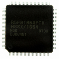
DF61654N50FTV Renesas Electronics America, DF61654N50FTV Datasheet - Page 15

DF61654N50FTV
Manufacturer Part Number
DF61654N50FTV
Description
IC H8SX/1654 MCU FLASH 120TQFP
Manufacturer
Renesas Electronics America
Series
H8® H8SX/1600r
Datasheet
1.DF61653N50FTV.pdf
(1020 pages)
Specifications of DF61654N50FTV
Core Processor
H8SX
Core Size
32-Bit
Speed
50MHz
Connectivity
I²C, IrDA, SCI, SmartCard, USB
Peripherals
DMA, PWM, WDT
Number Of I /o
75
Program Memory Size
512KB (512K x 8)
Program Memory Type
FLASH
Ram Size
40K x 8
Voltage - Supply (vcc/vdd)
3 V ~ 3.6 V
Data Converters
A/D 8x10b; D/A 2x8b
Oscillator Type
External
Operating Temperature
-20°C ~ 75°C
Package / Case
120-TQFP, 120-VQFP
For Use With
HS0005KCU11H - EMULATOR E10A-USB H8S(X),SH2(A)3DK1657 - DEV EVAL KIT FOR H8SX/1657
Lead Free Status / RoHS Status
Lead free / RoHS Compliant
Eeprom Size
-
Available stocks
Company
Part Number
Manufacturer
Quantity
Price
Company:
Part Number:
DF61654N50FTV
Manufacturer:
Renesas Electronics America
Quantity:
10 000
- Current page: 15 of 1020
- Download datasheet (6Mb)
6.8
6.9
6.10 Idle Cycle........................................................................................................................... 208
6.11 Bus Release........................................................................................................................ 218
6.12 Internal Bus........................................................................................................................ 221
6.13 Write Data Buffer Function ............................................................................................... 222
6.14 Bus Arbitration................................................................................................................... 224
6.15 Bus Controller Operation in Reset ..................................................................................... 227
6.16 Usage Notes ....................................................................................................................... 227
6.7.5
6.7.6
6.7.7
6.7.8
Burst ROM Interface.......................................................................................................... 193
6.8.1
6.8.2
6.8.3
6.8.4
6.8.5
6.8.6
6.8.7
Address/Data Multiplexed I/O Interface ............................................................................ 198
6.9.1
6.9.2
6.9.3
6.9.4
6.9.5
6.9.6
6.9.7
6.9.8
6.9.9
6.9.10 DACK Signal Output Timing ............................................................................... 207
6.10.1 Operation .............................................................................................................. 208
6.10.2 Pin States in Idle Cycle ......................................................................................... 217
6.11.1 Operation .............................................................................................................. 218
6.11.2 Pin States in External Bus Released State............................................................. 219
6.11.3 Transition Timing ................................................................................................. 220
6.12.1 Access to Internal Address Space ......................................................................... 221
6.13.1 Write Data Buffer Function for External Data Bus............................................... 222
6.13.2 Write Data Buffer Function for Peripheral Modules ............................................ 223
6.14.1 Operation .............................................................................................................. 224
6.14.2 Bus Transfer Timing............................................................................................. 225
Wait Control ......................................................................................................... 189
Read Strobe (RD).................................................................................................. 191
Extension of Chip Select (CS) Assertion Period................................................... 191
DACK Signal Output Timing ............................................................................... 191
Burst ROM Space Setting..................................................................................... 193
Data Bus................................................................................................................ 193
I/O Pins Used for Burst ROM Interface................................................................ 194
Basic Timing......................................................................................................... 195
Wait Control ......................................................................................................... 197
Read Strobe (RD) Timing..................................................................................... 197
Extension of Chip Select (CS) Assertion Period................................................... 197
Address/Data Multiplexed I/O Space Setting ....................................................... 198
Address/Data Multiplex ........................................................................................ 198
Data Bus................................................................................................................ 198
I/O Pins Used for Address/Data Multiplexed I/O Interface .................................. 199
Basic Timing......................................................................................................... 200
Address Cycle Control.......................................................................................... 202
Wait Control ......................................................................................................... 203
Read Strobe (RD) Timing.................................................................................... 203
Extension of Chip Select (CS) Assertion Period................................................... 205
Rev.1.00 Sep. 08, 2005 Page xiii of xlviiil
Related parts for DF61654N50FTV
Image
Part Number
Description
Manufacturer
Datasheet
Request
R

Part Number:
Description:
KIT STARTER FOR M16C/29
Manufacturer:
Renesas Electronics America
Datasheet:

Part Number:
Description:
KIT STARTER FOR R8C/2D
Manufacturer:
Renesas Electronics America
Datasheet:

Part Number:
Description:
R0K33062P STARTER KIT
Manufacturer:
Renesas Electronics America
Datasheet:

Part Number:
Description:
KIT STARTER FOR R8C/23 E8A
Manufacturer:
Renesas Electronics America
Datasheet:

Part Number:
Description:
KIT STARTER FOR R8C/25
Manufacturer:
Renesas Electronics America
Datasheet:

Part Number:
Description:
KIT STARTER H8S2456 SHARPE DSPLY
Manufacturer:
Renesas Electronics America
Datasheet:

Part Number:
Description:
KIT STARTER FOR R8C38C
Manufacturer:
Renesas Electronics America
Datasheet:

Part Number:
Description:
KIT STARTER FOR R8C35C
Manufacturer:
Renesas Electronics America
Datasheet:

Part Number:
Description:
KIT STARTER FOR R8CL3AC+LCD APPS
Manufacturer:
Renesas Electronics America
Datasheet:

Part Number:
Description:
KIT STARTER FOR RX610
Manufacturer:
Renesas Electronics America
Datasheet:

Part Number:
Description:
KIT STARTER FOR R32C/118
Manufacturer:
Renesas Electronics America
Datasheet:

Part Number:
Description:
KIT DEV RSK-R8C/26-29
Manufacturer:
Renesas Electronics America
Datasheet:

Part Number:
Description:
KIT STARTER FOR SH7124
Manufacturer:
Renesas Electronics America
Datasheet:

Part Number:
Description:
KIT STARTER FOR H8SX/1622
Manufacturer:
Renesas Electronics America
Datasheet:

Part Number:
Description:
KIT DEV FOR SH7203
Manufacturer:
Renesas Electronics America
Datasheet:


