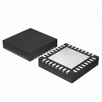
EFM32G200F64 Energy Micro, EFM32G200F64 Datasheet - Page 99

EFM32G200F64
Manufacturer Part Number
EFM32G200F64
Description
MCU 32BIT 64KB FLASH 32-QFN
Manufacturer
Energy Micro
Series
Geckor
Datasheets
1.EFM32G200F16.pdf
(63 pages)
2.EFM32G200F16.pdf
(10 pages)
3.EFM32G200F16.pdf
(463 pages)
4.EFM32G200F16.pdf
(136 pages)
Specifications of EFM32G200F64
Core Processor
ARM® Cortex-M3™
Core Size
32-Bit
Speed
32MHz
Connectivity
EBI/EMI, I²C, IrDA, SmartCard, SPI, UART/USART
Peripherals
Brown-out Detect/Reset, DMA, POR, PWM, WDT
Number Of I /o
24
Program Memory Size
64KB (64K x 8)
Program Memory Type
FLASH
Ram Size
16K x 8
Voltage - Supply (vcc/vdd)
1.8 V ~ 3.8 V
Data Converters
A/D 4x12b, D/A 1x12b
Oscillator Type
External
Operating Temperature
-40°C ~ 85°C
Package / Case
32-VQFN Exposed Pad
Processor Series
EFM32G200
Core
ARM Cortex-M3
Data Bus Width
32 bit
Data Ram Size
16 KB
Interface Type
I2C, UART
Maximum Clock Frequency
32 MHz
Number Of Programmable I/os
24
Number Of Timers
2
Operating Supply Voltage
1.8 V to 3.8 V
Maximum Operating Temperature
+ 85 C
Mounting Style
SMD/SMT
Minimum Operating Temperature
- 40 C
Lead Free Status / RoHS Status
Lead free / RoHS Compliant
Eeprom Size
-
Lead Free Status / Rohs Status
Details
Available stocks
Company
Part Number
Manufacturer
Quantity
Price
4.3.6 Application Interrupt and Reset Control Register
2011-02-04 - d0002_Rev1.00
Table 4.16. VTOR bit assignments
When setting TBLOFF, you must align the offset to the number of exception entries in the vector table.
The recommended alignment is 64 words, which covers all EFM32 interrupts and the 16 internal Cortex-
M3 exceptions. If you require 16 interrupts or less, the alignment can be set to 32 words.
Note
The AIRCR provides priority grouping control for the exception model, endian status for data accesses,
and reset control of the system. See the register summary in Table 4.12 (p. 94) and Table 4.17 (p.
99) for its attributes.
To write to this register, you must write 0x5VA to the VECTKEY field, otherwise the processor ignores
the write.
The bit assignments are:
Table 4.17. AIRCR bit assignments
31
Bits
[31:30]
[29(31):7] TBLOFF
[6:0]
Bits
[31:16]
[15]
[14:11]
[10:8]
[7:3]
Name
-
-
Name
Write: VECTKEYSTAT
Read: VECTKEY
ENDIANESS
-
PRIGROUP
-
Table alignment requirements mean that bits[6:0] of the table offset are always zero.
On read: VECTKEYSTAT
On write: VECTKEY
Function
Reserved (in some devices these bits are part of the TBLOFF bitfield as explained below).
Vector table base offset field. It contains bits[29:7] (bits[31:7] for Cortex-M3 revision r2p1 and
later) of the offset of the table base from the bottom of the memory map. Table 1.1 (p. 5) shows
the Cortex-M3 revision number for the EFM32 device series.
Note
Reserved.
Bit[29] (bit 31 in Cortex-M3 revision r2p1 and later) determines whether the vector table
is in the code or SRAM memory region:
• 0 = code
• 1 = SRAM.
Bit[29(31)] is sometimes called the TBLBASE bit.
Type
RW
RO
-
R/W
-
ENDIANESS
Reserved for Debug use
Function
Register key:
Reads as 0x05FA
On writes, write 0x5FA to VECTKEY, otherwise the write is ignored.
Always read as 0 (Little-endian)
Reserved
Interrupt priority grouping field. This field determines the split of group
priority from subpriority, see Section 4.3.6.1 (p. 100) .
Reserved.
16 15 14
...the world's most energy friendly microcontrollers
Reserved
PRIGROUP
99
11 10
VECTCLRACTIVE
SYSRESETREQ
8 7
VECTRESET
Reserved
3 2 1 0
www.energymicro.com


