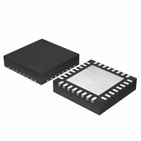
EFM32G200F64 Energy Micro, EFM32G200F64 Datasheet - Page 110

EFM32G200F64
Manufacturer Part Number
EFM32G200F64
Description
MCU 32BIT 64KB FLASH 32-QFN
Manufacturer
Energy Micro
Series
Geckor
Datasheets
1.EFM32G200F16.pdf
(63 pages)
2.EFM32G200F16.pdf
(10 pages)
3.EFM32G200F16.pdf
(463 pages)
4.EFM32G200F16.pdf
(136 pages)
Specifications of EFM32G200F64
Core Processor
ARM® Cortex-M3™
Core Size
32-Bit
Speed
32MHz
Connectivity
EBI/EMI, I²C, IrDA, SmartCard, SPI, UART/USART
Peripherals
Brown-out Detect/Reset, DMA, POR, PWM, WDT
Number Of I /o
24
Program Memory Size
64KB (64K x 8)
Program Memory Type
FLASH
Ram Size
16K x 8
Voltage - Supply (vcc/vdd)
1.8 V ~ 3.8 V
Data Converters
A/D 4x12b, D/A 1x12b
Oscillator Type
External
Operating Temperature
-40°C ~ 85°C
Package / Case
32-VQFN Exposed Pad
Processor Series
EFM32G200
Core
ARM Cortex-M3
Data Bus Width
32 bit
Data Ram Size
16 KB
Interface Type
I2C, UART
Maximum Clock Frequency
32 MHz
Number Of Programmable I/os
24
Number Of Timers
2
Operating Supply Voltage
1.8 V to 3.8 V
Maximum Operating Temperature
+ 85 C
Mounting Style
SMD/SMT
Minimum Operating Temperature
- 40 C
Lead Free Status / RoHS Status
Lead free / RoHS Compliant
Eeprom Size
-
Lead Free Status / Rohs Status
Details
Available stocks
Company
Part Number
Manufacturer
Quantity
Price
4.3.13 Memory Management Fault Address Register
4.3.14 Bus Fault Address Register
4.3.15 System control block design hints and tips
2011-02-04 - d0002_Rev1.00
Note
The MMFAR contains the address of the location that generated a memory management fault. See the
register summary in Table 4.12 (p. 94) for its attributes. The bit assignments are:
Table 4.30. MMFAR bit assignments
When an unaligned access faults, the address is the actual address that faulted. Because a single read
or write instruction can be split into multiple aligned accesses, the fault address can be any address in
the range of the requested access size.
Flags in the MMFSR indicate the cause of the fault, and whether the value in the MMFAR is valid. See
Section 4.3.11.1 (p. 105) .
The BFAR contains the address of the location that generated a bus fault. See the register summary in
Table 4.12 (p. 94) for its attributes. The bit assignments are:
Table 4.31. BFAR bit assignments
When an unaligned access faults the address in the BFAR is the one requested by the instruction, even
if it is not the address of the fault.
Flags in the BFSR indicate the cause of the fault, and whether the value in the BFAR is valid. See
Section 4.3.11.2 (p. 107) .
Ensure software uses aligned accesses of the correct size to access the system control block registers:
• except for the CFSR and SHPR1-SHPR3, it must use aligned word accesses
• for the CFSR and SHPR1-SHPR3 it can use byte or aligned halfword or word accesses.
The processor does not support unaligned accesses to system control block registers.
In a fault handler. to determine the true faulting address:
1. Read and save the MMFAR or BFAR value.
2. Read the MMARVALID bit in the MMFSR, or the BFARVALID bit in the BFSR. The MMFAR or BFAR
Bits
[0]
Bits
[31:0]
Bits
[31:0]
address is valid only if this bit is 1.
Name
-
Name
ADDRESS
Name
ADDRESS
The HFSR bits are sticky. This means as one or more fault occurs, the associated bits are
set to 1. A bit that is set to 1 is cleared to 0 only by writing 1 to that bit, or by a reset.
Function
When the BFARVALID bit of the BFSR is set to 1, this field holds the address of the location that
generated the bus fault
Function
When the MMARVALID bit of the MMFSR is set to 1, this field holds the address of the location
that generated the memory management fault
Function
When this bit is set to 1, the PC value stacked for the exception return points to the instruction
that was preempted by the exception.
Reserved.
...the world's most energy friendly microcontrollers
110
www.energymicro.com


