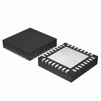
EFM32G200F64 Energy Micro, EFM32G200F64 Datasheet - Page 43

EFM32G200F64
Manufacturer Part Number
EFM32G200F64
Description
MCU 32BIT 64KB FLASH 32-QFN
Manufacturer
Energy Micro
Series
Geckor
Datasheets
1.EFM32G200F16.pdf
(63 pages)
2.EFM32G200F16.pdf
(10 pages)
3.EFM32G200F16.pdf
(463 pages)
4.EFM32G200F16.pdf
(136 pages)
Specifications of EFM32G200F64
Core Processor
ARM® Cortex-M3™
Core Size
32-Bit
Speed
32MHz
Connectivity
EBI/EMI, I²C, IrDA, SmartCard, SPI, UART/USART
Peripherals
Brown-out Detect/Reset, DMA, POR, PWM, WDT
Number Of I /o
24
Program Memory Size
64KB (64K x 8)
Program Memory Type
FLASH
Ram Size
16K x 8
Voltage - Supply (vcc/vdd)
1.8 V ~ 3.8 V
Data Converters
A/D 4x12b, D/A 1x12b
Oscillator Type
External
Operating Temperature
-40°C ~ 85°C
Package / Case
32-VQFN Exposed Pad
Processor Series
EFM32G200
Core
ARM Cortex-M3
Data Bus Width
32 bit
Data Ram Size
16 KB
Interface Type
I2C, UART
Maximum Clock Frequency
32 MHz
Number Of Programmable I/os
24
Number Of Timers
2
Operating Supply Voltage
1.8 V to 3.8 V
Maximum Operating Temperature
+ 85 C
Mounting Style
SMD/SMT
Minimum Operating Temperature
- 40 C
Lead Free Status / RoHS Status
Lead free / RoHS Compliant
Eeprom Size
-
Lead Free Status / Rohs Status
Details
Available stocks
Company
Part Number
Manufacturer
Quantity
Price
3.3.7 Conditional execution
3.3.7.1 The condition flags
2011-02-04 - d0002_Rev1.00
Note
Most data processing instructions can optionally update the condition flags in the Application Program
Status Register (APSR) according to the result of the operation, see Section 2.1.3.5.1 (p. 9) . Some
instructions update all flags, and some only update a subset. If a flag is not updated, the original value
is preserved. See the instruction descriptions for the flags they affect.
You can execute an instruction conditionally, based on the condition flags set in another instruction,
either:
• immediately after the instruction that updated the flags
• after any number of intervening instructions that have not updated the flags.
Conditional execution is available by using conditional branches or by adding condition code suffixes
to instructions. See Table 3.4 (p. 44) for a list of the suffixes to add to instructions to make them
conditional instructions. The condition code suffix enables the processor to test a condition based on
the flags. If the condition test of a conditional instruction fails, the instruction:
• does not execute
• does not write any value to its destination register
• does not affect any of the flags
• does not generate any exception.
Conditional instructions, except for conditional branches, must be inside an If-Then instruction block. See
Section 3.9.3 (p. 76) for more information and restrictions when using the IT instruction. Depending
on the vendor, the assembler might automatically insert an IT instruction if you have conditional
instructions outside the IT block.
Use the CBZ and CBNZ instructions to compare the value of a register against zero and branch on the
result.
This section describes:
• Section 3.3.7.1 (p. 43)
• Section 3.3.7.2 (p. 44) .
The APSR contains the following condition flags:
N Set to 1 when the result of the operation was negative, cleared to 0 otherwise.
Z Set to 1 when the result of the operation was zero, cleared to 0 otherwise.
C Set to 1 when the operation resulted in a carry, cleared to 0 otherwise.
V Set to 1 when the operation caused overflow, cleared to 0 otherwise.
For more information about the APSR see Section 2.1.3.5 (p. 8) .
A carry occurs:
• For B, BL, CBNZ, and CBZ instructions, the value of the PC is the address of the current
• For all other instructions that use labels, the value of the PC is the address of the current
• Your assembler might permit other syntaxes for PC-relative expressions, such as a label
instruction plus 4 bytes.
instruction plus 4 bytes, with bit[1] of the result cleared to 0 to make it word-aligned.
plus or minus a number, or an expression of the form [PC, #number].
...the world's most energy friendly microcontrollers
43
www.energymicro.com


