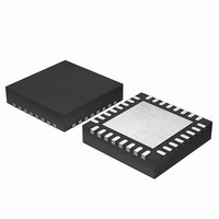
EFM32G200F64 Energy Micro, EFM32G200F64 Datasheet - Page 89

EFM32G200F64
Manufacturer Part Number
EFM32G200F64
Description
MCU 32BIT 64KB FLASH 32-QFN
Manufacturer
Energy Micro
Series
Geckor
Datasheets
1.EFM32G200F16.pdf
(63 pages)
2.EFM32G200F16.pdf
(10 pages)
3.EFM32G200F16.pdf
(463 pages)
4.EFM32G200F16.pdf
(136 pages)
Specifications of EFM32G200F64
Core Processor
ARM® Cortex-M3™
Core Size
32-Bit
Speed
32MHz
Connectivity
EBI/EMI, I²C, IrDA, SmartCard, SPI, UART/USART
Peripherals
Brown-out Detect/Reset, DMA, POR, PWM, WDT
Number Of I /o
24
Program Memory Size
64KB (64K x 8)
Program Memory Type
FLASH
Ram Size
16K x 8
Voltage - Supply (vcc/vdd)
1.8 V ~ 3.8 V
Data Converters
A/D 4x12b, D/A 1x12b
Oscillator Type
External
Operating Temperature
-40°C ~ 85°C
Package / Case
32-VQFN Exposed Pad
Processor Series
EFM32G200
Core
ARM Cortex-M3
Data Bus Width
32 bit
Data Ram Size
16 KB
Interface Type
I2C, UART
Maximum Clock Frequency
32 MHz
Number Of Programmable I/os
24
Number Of Timers
2
Operating Supply Voltage
1.8 V to 3.8 V
Maximum Operating Temperature
+ 85 C
Mounting Style
SMD/SMT
Minimum Operating Temperature
- 40 C
Lead Free Status / RoHS Status
Lead free / RoHS Compliant
Eeprom Size
-
Lead Free Status / Rohs Status
Details
Available stocks
Company
Part Number
Manufacturer
Quantity
Price
4.2.1 The CMSIS mapping of the Cortex-M3 NVIC registers
4.2.2 Interrupt Set-enable Registers
2011-02-04 - d0002_Rev1.00
1
2
To improve software efficiency, the CMSIS simplifies the NVIC register presentation. In the CMSIS:
• the Set-enable, Clear-enable, Set-pending, Clear-pending and Active Bit registers map to arrays of
• the 8-bit fields of the Interrupt Priority Registers map to an array of 8-bit integers, so that the array
The CMSIS provides thread-safe code that gives atomic access to the Interrupt Priority Registers. For
more information see the description of the NVIC_SetPriority function in Section 4.2.10.1 (p. 94)
. Table 4.3 (p. 89) shows how the interrupts, or IRQ numbers, map onto the interrupt registers and
corresponding CMSIS variables that have one bit per interrupt.
Table 4.3. Mapping of interrupts to the interrupt variables
1
The ISER0 and ISER1 registers enable interrupts, and show which interrupts are enabled. See:
• the register summary in Table 4.2 (p. 88) for the register attributes
• Table 4.3 (p. 89) for which interrupts are controlled by each register.
The bit assignments are:
31
m=(n-1)/4, where n denotes the number of interrupts given in Table 1.1 (p. 5) .
See the register description for more information.
Each array element corresponds to a single NVIC register, for example the element ICER[1] corresponds to the ICER1 register.
Address
0XE000E200-
0XE000E204
0XE000E280-
0XE000E284
0xE000E300-
0xE000E304
0xE000E400-
0xE000E400+4xm
0xE000EF00
Interrupts
0-31
32-63
32-bit integers, so that:
• ISER[0] to ISER[1]corresponds to the registers ISER0-ISER1
• ICER[0] to ICER[1]corresponds to the registers ICER0-ICER1
• ISPR[0] to ISPR[1]corresponds to the registers ISPR0-ISPR1
• ICPR[0] to ICPR[1]corresponds to the registers ICPR0-ICPR1
• IABR[0] to IABR[1]corresponds to the registers IABR0-IABR1
IP[0] to IP[n-1] corresponds to the registers IPR0-IPRm (m=(n-1)/4, where n denotes the number
of interrupts given by Table 1.1 (p. 5) ), and the array entry IP[N] holds the interrupt priority for
interrupt N.
CMSIS array elements
Set-enable
ISER[0]
ISER[1]
Name
ISPR0-
ISPR1
ICPR0-
ICPR1
IABR0-
IABR1
IPR0-
IPRm
STIR
Clear-enable
ICER[0]
ICER[1]
Type
RW
RW
RO
RW
WO
1
Required
privilege
Privileged
Privileged
Privileged
Privileged
Configurable
Set-pending
ISPR[0]
ISPR[1]
2
SETENA bits
Reset value Description
0x00000000 Section 4.2.4 (p. 90)
0x00000000 Section 4.2.5 (p. 91)
0x00000000 Section 4.2.6 (p. 91)
0x00000000 Section 4.2.7 (p. 92)
0x00000000 Section 4.2.8 (p. 93)
...the world's most energy friendly microcontrollers
89
Clear-pending
ICPR[0]
ICPR[1]
Active Bit
IABR[0]
IABR[1]
1
www.energymicro.com
0


