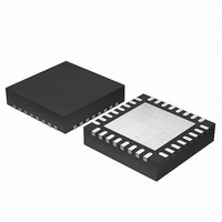
EFM32G200F64 Energy Micro, EFM32G200F64 Datasheet - Page 92

EFM32G200F64
Manufacturer Part Number
EFM32G200F64
Description
MCU 32BIT 64KB FLASH 32-QFN
Manufacturer
Energy Micro
Series
Geckor
Datasheets
1.EFM32G200F16.pdf
(63 pages)
2.EFM32G200F16.pdf
(10 pages)
3.EFM32G200F16.pdf
(463 pages)
4.EFM32G200F16.pdf
(136 pages)
Specifications of EFM32G200F64
Core Processor
ARM® Cortex-M3™
Core Size
32-Bit
Speed
32MHz
Connectivity
EBI/EMI, I²C, IrDA, SmartCard, SPI, UART/USART
Peripherals
Brown-out Detect/Reset, DMA, POR, PWM, WDT
Number Of I /o
24
Program Memory Size
64KB (64K x 8)
Program Memory Type
FLASH
Ram Size
16K x 8
Voltage - Supply (vcc/vdd)
1.8 V ~ 3.8 V
Data Converters
A/D 4x12b, D/A 1x12b
Oscillator Type
External
Operating Temperature
-40°C ~ 85°C
Package / Case
32-VQFN Exposed Pad
Processor Series
EFM32G200
Core
ARM Cortex-M3
Data Bus Width
32 bit
Data Ram Size
16 KB
Interface Type
I2C, UART
Maximum Clock Frequency
32 MHz
Number Of Programmable I/os
24
Number Of Timers
2
Operating Supply Voltage
1.8 V to 3.8 V
Maximum Operating Temperature
+ 85 C
Mounting Style
SMD/SMT
Minimum Operating Temperature
- 40 C
Lead Free Status / RoHS Status
Lead free / RoHS Compliant
Eeprom Size
-
Lead Free Status / Rohs Status
Details
Available stocks
Company
Part Number
Manufacturer
Quantity
Price
4.2.7 Interrupt Priority Registers
2011-02-04 - d0002_Rev1.00
Table 4.8. IABR bit assignments
A bit reads as one if the status of the corresponding interrupt is active or active and pending.
The IPR0-IPRm registers provide an 3-bit priority field for each interrupt. These registers are byte-
accessible. See the register summary in Table 4.2 (p. 88) for their attributes. Each register holds
four priority fields, that map to four elements in the CMSIS interrupt priority array IP[0] to IP[n-1],
as shown:
Table 4.9. IPR bit assignments
See Section 4.2.1 (p. 89) for more information about the IP[0] to IP[n-1] interrupt priority array,
that provides the software view of the interrupt priorities.
Find the IPR number and byte offset for interrupt N (n, the maximum number for N is given by Table 1.1 (p.
5) and subtracted by 1) as follows:
• the corresponding IPR number, k, is given by k = N DIV 4
• the byte offset of the required Priority field in this register is N MOD 4, where:
31
Bits
[31:0]
Bits
[31:24]
[23:16]
[15:8]
[7:0]
IPRm
IPR0
IPRk
• byte offset 0 refers to register bits[7:0]
• byte offset 1 refers to register bits[15:8]
Name
ACTIVE
31
Name
Priority, byte offset 3
Priority, byte offset 2
Priority, byte offset 1
Priority, byte offset 0
IP[ 4k+ 3]
IP[ n-1]
Function
Interrupt active flags:
0 = interrupt not active
1 = interrupt active.
IP[ 3]
Function
Each priority field holds a priority value, 0-7. The lower the value, the greater the
priority of the corresponding interrupt. Only bits[7:5] of each field are implemented,
bits[4:0] read as zero and ignore writes.
24 23
IP[ 4k+ 2]
IP[ n-2]
IP[ 2]
ACTIVE bits
...the world's most energy friendly microcontrollers
92
16 15
IP[ 4k+ 1]
IP[ n-2]
IP[ 1]
www.energymicro.com
8 7
IP[ n-3]
IP[ 4k]
IP[ 0]
0
0


