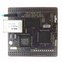
EZ80F920120MOD Zilog, EZ80F920120MOD Datasheet - Page 94

EZ80F920120MOD
Manufacturer Part Number
EZ80F920120MOD
Description
MODULE EZ80F92 512K 20MHZ
Manufacturer
Zilog
Datasheets
1.EZ80F920120MOD.pdf
(269 pages)
2.EZ80F920120MOD.pdf
(4 pages)
3.EZ80F920120MOD.pdf
(2 pages)
Specifications of EZ80F920120MOD
Module/board Type
Development Module
Processor Series
EZ80F92x
Core
eZ80
Data Bus Width
8 bit
Program Memory Type
Flash
Program Memory Size
1 MB
Interface Type
Cable
Maximum Clock Frequency
20 MHz
Operating Supply Voltage
0 V to 3.3 V
Maximum Operating Temperature
+ 70 C
Mounting Style
SMD/SMT
Package / Case
LQFP
Development Tools By Supplier
eZ80F920200ZCOG
Minimum Operating Temperature
0 C
For Use With/related Products
eZ80F92
Lead Free Status / RoHS Status
Contains lead / RoHS non-compliant
Other names
269-3157
EZ80F920120MOD
EZ80F920120MOD
- Current page: 94 of 269
- Download datasheet (4Mb)
eZ80F92/eZ80F93
Product Specification
82
Then, when the end-of-count value,
, is reached and PRT_IRQ is set to 1, an inter-
0000h
rupt service request signal is passed to the CPU. PRT_IRQ is cleared to 0 and the interrupt
service request signal is inactivated whenever the CPU reads from the timer control regis-
ters, TMRx_CTL.
Timer Input Source Selection
Timers 0–3 feature programmable input source selection. By default, the input is taken
from the eZ80F92 device’s system clock. Alternatively, Timers 0–3 can take their input
from port input pins PB0 (Timers 0 and 2) or PB1 (Timers 1 and 3). Timers 0–3 can also
use the Real-Time Clock source (50, 60, or 32768Hz) as their clock sources. When the
timer clock source is the Real-Time Clock signal, the timer decrements on the second ris-
ing edge of the system clock following the falling edge of the RTC_X
pin. The input
OUT
source for these timers is set using the Timer Input Source Select register.
Event Counter
When Timers 0–3 are configured to take their inputs from port input pins PB0 and PB1,
they function as event counters. For event counting, the clock prescaler is bypassed. The
PRT counters decrement on every rising edge of the port pin. The port pins must be con-
figured as inputs. Due to the input sampling on the pins, the event input signal frequency is
limited to one-half the system clock frequency. Input sampling on the port pins results in
the PRT counter being updated on the fifth rising edge of the system clock after the rising
edge occurs at the port pin.
Timer Output
Two of the Programmable Reload Timers (Timers 4 and 5) can be directed to GPIO Port B
output pins (PB4 and PB5, respectively). To enable the Timer Out feature, the GPIO port
pin must be configured for alternate functions. After reset, the Timer Output feature is dis-
abled by default. The GPIO output pin toggles each time the PRT reaches its end-of-count
value. In CONTINUOUS mode operation, the disabling of the Timer Output feature
results in a Timer Output signal period that is twice the PRT time-out period. Examples of
the Timer Output operation are illustrated in Figure 22 and PRT Timer Out Operation
Example. In these examples, the GPIO output is assumed to be Low (0) when the Timer
Output function is enabled.
PS015308-0404
P R E L I M I N A R Y
Programmable Reload Timers
Related parts for EZ80F920120MOD
Image
Part Number
Description
Manufacturer
Datasheet
Request
R

Part Number:
Description:
Communication Controllers, ZILOG INTELLIGENT PERIPHERAL CONTROLLER (ZIP)
Manufacturer:
Zilog, Inc.
Datasheet:

Part Number:
Description:
KIT DEV FOR Z8 ENCORE 16K TO 64K
Manufacturer:
Zilog
Datasheet:

Part Number:
Description:
KIT DEV Z8 ENCORE XP 28-PIN
Manufacturer:
Zilog
Datasheet:

Part Number:
Description:
DEV KIT FOR Z8 ENCORE 8K/4K
Manufacturer:
Zilog
Datasheet:

Part Number:
Description:
KIT DEV Z8 ENCORE XP 28-PIN
Manufacturer:
Zilog
Datasheet:

Part Number:
Description:
DEV KIT FOR Z8 ENCORE 4K TO 8K
Manufacturer:
Zilog
Datasheet:

Part Number:
Description:
CMOS Z8 microcontroller. ROM 16 Kbytes, RAM 256 bytes, speed 16 MHz, 32 lines I/O, 3.0V to 5.5V
Manufacturer:
Zilog, Inc.
Datasheet:

Part Number:
Description:
Low-cost microcontroller. 512 bytes ROM, 61 bytes RAM, 8 MHz
Manufacturer:
Zilog, Inc.
Datasheet:

Part Number:
Description:
Z8 4K OTP Microcontroller
Manufacturer:
Zilog, Inc.
Datasheet:

Part Number:
Description:
CMOS SUPER8 ROMLESS MCU
Manufacturer:
Zilog, Inc.
Datasheet:

Part Number:
Description:
SL1866 CMOSZ8 OTP Microcontroller
Manufacturer:
Zilog, Inc.
Datasheet:

Part Number:
Description:
SL1866 CMOSZ8 OTP Microcontroller
Manufacturer:
Zilog, Inc.
Datasheet:

Part Number:
Description:
OTP (KB) = 1, RAM = 125, Speed = 12, I/O = 14, 8-bit Timers = 2, Comm Interfaces Other Features = Por, LV Protect, Voltage = 4.5-5.5V
Manufacturer:
Zilog, Inc.
Datasheet:

Part Number:
Description:
Manufacturer:
Zilog, Inc.
Datasheet:


