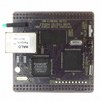
EZ80F920120MOD Zilog, EZ80F920120MOD Datasheet - Page 140

EZ80F920120MOD
Manufacturer Part Number
EZ80F920120MOD
Description
MODULE EZ80F92 512K 20MHZ
Manufacturer
Zilog
Datasheets
1.EZ80F920120MOD.pdf
(269 pages)
2.EZ80F920120MOD.pdf
(4 pages)
3.EZ80F920120MOD.pdf
(2 pages)
Specifications of EZ80F920120MOD
Module/board Type
Development Module
Processor Series
EZ80F92x
Core
eZ80
Data Bus Width
8 bit
Program Memory Type
Flash
Program Memory Size
1 MB
Interface Type
Cable
Maximum Clock Frequency
20 MHz
Operating Supply Voltage
0 V to 3.3 V
Maximum Operating Temperature
+ 70 C
Mounting Style
SMD/SMT
Package / Case
LQFP
Development Tools By Supplier
eZ80F920200ZCOG
Minimum Operating Temperature
0 C
For Use With/related Products
eZ80F92
Lead Free Status / RoHS Status
Contains lead / RoHS non-compliant
Other names
269-3157
EZ80F920120MOD
EZ80F920120MOD
- Current page: 140 of 269
- Download datasheet (4Mb)
Figure 27.Infrared Data Reception
PS015308-0404
UART
Baud Rate
IR
8-clock
delay
Clock
RxD
RxD
The UART baud rate clock is used by the IrDA endec to generate the demodulated signal
(RxD) that drives the UART. Each UART bit period is sixteen baud-clocks wide. Each
IR_RXD bit is encoded during a bit period such that a 0 is represented by a pulse and a 1
is represented by no pulse. The IrDA Physical Layer Specification describes a nominal
pulse as being
(Low), a 3-clock-wide Low (0) pulse is received following a 7-clock High (1) period. Fol-
lowing the 3-clock Low pulse is a 6-clock High pulse to complete the full 16-clock data
period. If the data to be received is a logical 1 (High), the IR_RxD signal is held High (1)
for the full 16-clock period. Data reception is illustrated in Figure 27.
The IrDA Physical Layer Specification allows for a minimum signal width as well as the
nominal signal width described above. By definition, the received pulse duration can be as
small as 1.41 seconds for all baud rates up to 115.2 KBPS. IrDA Physical Layer 1.4 Pulse
Durations Specifications outlines the minimum and maximum pulse durations for all baud
rates supported by the eZ80
clock frequency measures this time limit and allows legal signals to pass to UART0.
Table 68. IrDA Physical Layer 1.4 Pulse Durations Specifications
Baud Rate
Start Bit = 0
16-clock
19200
38400
period
9600
1.4 µs
min. pulse
16-clock
3
period
/
16
of a bit period wide. In this case, if the data to be received is a logical 0
Data Bit 0 = 1
Minimum Pulse
P R E L I M I N A R Y
®
Width
1.41 s
1.41 s
1.41 s
CPU. A receiver frequency divider based upon the system
16-clock
period
Data Bit 1 = 0
Maximum Pulse
16-clock
period
22.13 s
11.07 s
Width
5.96 s
Data Bit 2 = 1
16-clock
period
Product Specification
Infrared Encoder/Decoder
Data Bit 3 = 1
eZ80F92/eZ80F93
128
Related parts for EZ80F920120MOD
Image
Part Number
Description
Manufacturer
Datasheet
Request
R

Part Number:
Description:
Communication Controllers, ZILOG INTELLIGENT PERIPHERAL CONTROLLER (ZIP)
Manufacturer:
Zilog, Inc.
Datasheet:

Part Number:
Description:
KIT DEV FOR Z8 ENCORE 16K TO 64K
Manufacturer:
Zilog
Datasheet:

Part Number:
Description:
KIT DEV Z8 ENCORE XP 28-PIN
Manufacturer:
Zilog
Datasheet:

Part Number:
Description:
DEV KIT FOR Z8 ENCORE 8K/4K
Manufacturer:
Zilog
Datasheet:

Part Number:
Description:
KIT DEV Z8 ENCORE XP 28-PIN
Manufacturer:
Zilog
Datasheet:

Part Number:
Description:
DEV KIT FOR Z8 ENCORE 4K TO 8K
Manufacturer:
Zilog
Datasheet:

Part Number:
Description:
CMOS Z8 microcontroller. ROM 16 Kbytes, RAM 256 bytes, speed 16 MHz, 32 lines I/O, 3.0V to 5.5V
Manufacturer:
Zilog, Inc.
Datasheet:

Part Number:
Description:
Low-cost microcontroller. 512 bytes ROM, 61 bytes RAM, 8 MHz
Manufacturer:
Zilog, Inc.
Datasheet:

Part Number:
Description:
Z8 4K OTP Microcontroller
Manufacturer:
Zilog, Inc.
Datasheet:

Part Number:
Description:
CMOS SUPER8 ROMLESS MCU
Manufacturer:
Zilog, Inc.
Datasheet:

Part Number:
Description:
SL1866 CMOSZ8 OTP Microcontroller
Manufacturer:
Zilog, Inc.
Datasheet:

Part Number:
Description:
SL1866 CMOSZ8 OTP Microcontroller
Manufacturer:
Zilog, Inc.
Datasheet:

Part Number:
Description:
OTP (KB) = 1, RAM = 125, Speed = 12, I/O = 14, 8-bit Timers = 2, Comm Interfaces Other Features = Por, LV Protect, Voltage = 4.5-5.5V
Manufacturer:
Zilog, Inc.
Datasheet:

Part Number:
Description:
Manufacturer:
Zilog, Inc.
Datasheet:


