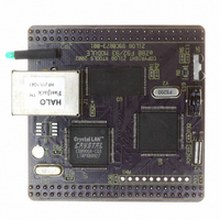
EZ80F920120MOD Zilog, EZ80F920120MOD Datasheet - Page 42

EZ80F920120MOD
Manufacturer Part Number
EZ80F920120MOD
Description
MODULE EZ80F92 512K 20MHZ
Manufacturer
Zilog
Datasheets
1.EZ80F920120MOD.pdf
(269 pages)
2.EZ80F920120MOD.pdf
(4 pages)
3.EZ80F920120MOD.pdf
(2 pages)
Specifications of EZ80F920120MOD
Module/board Type
Development Module
Processor Series
EZ80F92x
Core
eZ80
Data Bus Width
8 bit
Program Memory Type
Flash
Program Memory Size
1 MB
Interface Type
Cable
Maximum Clock Frequency
20 MHz
Operating Supply Voltage
0 V to 3.3 V
Maximum Operating Temperature
+ 70 C
Mounting Style
SMD/SMT
Package / Case
LQFP
Development Tools By Supplier
eZ80F920200ZCOG
Minimum Operating Temperature
0 C
For Use With/related Products
eZ80F92
Lead Free Status / RoHS Status
Contains lead / RoHS non-compliant
Other names
269-3157
EZ80F920120MOD
EZ80F920120MOD
- Current page: 42 of 269
- Download datasheet (4Mb)
Table 3. Register Map (Continued)
PS015308-0404
Address
(hex)
Universal Asynchronous Receiver/Transmitter 1 (UART1) Block
00D0
00D1
00D2
00D3
00D4
00D5
00D6
00D7
Low-Power Control
00DB
00DC
Real-Time Clock
00E0
00E1
00E2
00E3
Notes:
1. After an external pin reset, the Watch-Dog Timer Control register is reset to 00h. After a Watch-Dog Timer time-
2. When the CPU reads this register, the current sampled value of the port is read.
3. Read Only if RTC registers are locked; Read/Write if RTC registers are unlocked.
4. After an external pin reset or a Watch-Dog Timer reset, the RTC Control register is reset to x0xxxx00b. After an
5. Read Only if Flash Memory is locked. Read/Write if Flash Memory is unlocked.
out reset, the Watch-Dog Timer Control register is reset to 20h.
RTC Alarm sleep-mode recovery reset, the RTC Control register is reset to x0xxxx10b.
Mnemonic
UART1_RBR
UART1_THR
UART1_BRG_L
UART1_IER
UART1_BRG_H
UART1_IIR
UART1_FCTL
UART1_LCTL
UART1_MCTL
UART1_LSR
UART1_MSR
UART1_SPR
CLK_PPD1
CLK_PPD2
RTC_SEC
RTC_MIN
RTC_HRS
RTC_DOW
Name
UART 1 Receive Buffer Register
UART 1 Transmit Holding Register
UART 1 Baud Rate Generator Register—
Low Byte
UART 1 Interrupt Enable Register
UART 1 Baud Rate Generator Register—
High Byte
UART 1 Interrupt Identification Register
UART 1 FIFO Control Register
UART 1 Line Control Register
UART 1 Modem Control Register
UART 1 Line Status Register
UART 1 Modem Status Register
UART 1 Scratch Pad Register
Clock Peripheral Power-Down Register 1
Clock Peripheral Power-Down Register 2
RTC Seconds Register
RTC Minutes Register
RTC Hours Register
RTC Day-of-the-Week Register
P R E L I M I N A R Y
3
3
3
3
Reset
(hex)
XX
XX
XX
XX
XX
XX
0X
02
00
00
01
00
00
00
60
00
00
00
Product Specification
eZ80F92/eZ80F93
Access
CPU
R/W
R/W
R/W
R/W
R/W
R/W
R/W
R/W
R/W
R/W
R/W
R/W
R/W
R/W
W
W
R
R
Register Map
Page
121
122
124
125
114
114
112
115
113
116
117
118
39
40
92
93
94
95
#
30
Related parts for EZ80F920120MOD
Image
Part Number
Description
Manufacturer
Datasheet
Request
R

Part Number:
Description:
Communication Controllers, ZILOG INTELLIGENT PERIPHERAL CONTROLLER (ZIP)
Manufacturer:
Zilog, Inc.
Datasheet:

Part Number:
Description:
KIT DEV FOR Z8 ENCORE 16K TO 64K
Manufacturer:
Zilog
Datasheet:

Part Number:
Description:
KIT DEV Z8 ENCORE XP 28-PIN
Manufacturer:
Zilog
Datasheet:

Part Number:
Description:
DEV KIT FOR Z8 ENCORE 8K/4K
Manufacturer:
Zilog
Datasheet:

Part Number:
Description:
KIT DEV Z8 ENCORE XP 28-PIN
Manufacturer:
Zilog
Datasheet:

Part Number:
Description:
DEV KIT FOR Z8 ENCORE 4K TO 8K
Manufacturer:
Zilog
Datasheet:

Part Number:
Description:
CMOS Z8 microcontroller. ROM 16 Kbytes, RAM 256 bytes, speed 16 MHz, 32 lines I/O, 3.0V to 5.5V
Manufacturer:
Zilog, Inc.
Datasheet:

Part Number:
Description:
Low-cost microcontroller. 512 bytes ROM, 61 bytes RAM, 8 MHz
Manufacturer:
Zilog, Inc.
Datasheet:

Part Number:
Description:
Z8 4K OTP Microcontroller
Manufacturer:
Zilog, Inc.
Datasheet:

Part Number:
Description:
CMOS SUPER8 ROMLESS MCU
Manufacturer:
Zilog, Inc.
Datasheet:

Part Number:
Description:
SL1866 CMOSZ8 OTP Microcontroller
Manufacturer:
Zilog, Inc.
Datasheet:

Part Number:
Description:
SL1866 CMOSZ8 OTP Microcontroller
Manufacturer:
Zilog, Inc.
Datasheet:

Part Number:
Description:
OTP (KB) = 1, RAM = 125, Speed = 12, I/O = 14, 8-bit Timers = 2, Comm Interfaces Other Features = Por, LV Protect, Voltage = 4.5-5.5V
Manufacturer:
Zilog, Inc.
Datasheet:

Part Number:
Description:
Manufacturer:
Zilog, Inc.
Datasheet:


