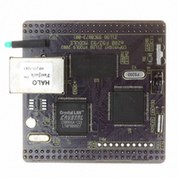
EZ80F920120MOD Zilog, EZ80F920120MOD Datasheet - Page 123

EZ80F920120MOD
Manufacturer Part Number
EZ80F920120MOD
Description
MODULE EZ80F92 512K 20MHZ
Manufacturer
Zilog
Datasheets
1.EZ80F920120MOD.pdf
(269 pages)
2.EZ80F920120MOD.pdf
(4 pages)
3.EZ80F920120MOD.pdf
(2 pages)
Specifications of EZ80F920120MOD
Module/board Type
Development Module
Processor Series
EZ80F92x
Core
eZ80
Data Bus Width
8 bit
Program Memory Type
Flash
Program Memory Size
1 MB
Interface Type
Cable
Maximum Clock Frequency
20 MHz
Operating Supply Voltage
0 V to 3.3 V
Maximum Operating Temperature
+ 70 C
Mounting Style
SMD/SMT
Package / Case
LQFP
Development Tools By Supplier
eZ80F920200ZCOG
Minimum Operating Temperature
0 C
For Use With/related Products
eZ80F92
Lead Free Status / RoHS Status
Contains lead / RoHS non-compliant
Other names
269-3157
EZ80F920120MOD
EZ80F920120MOD
- Current page: 123 of 269
- Download datasheet (4Mb)
PS015308-0404
Baud Rate Generator
then can discard the byte or take other appropriate action. If the interrupt is caused by a
receive-data-ready condition, the application alternately reads the UARTx_LSR and
UARTx_RBR registers and removes all of the received data bytes. It reads the
UARTx_LSR register before reading the UARTx_RBR register to determine that there is
no error in the received data.
To control and check modem status, the application sets up the modem by writing to the
UARTx_MCTL register and reading the UARTx_MSR register before starting the process
mentioned above.
Poll Mode Transfers.
poll mode transfers. In poll mode transfers, the application must continually poll the
UARTx_LSR register to transmit or receive data without enabling the interrupts. The same
is true for the UARTx_MSR register. If the interrupts are not enabled, the data in the
UARTx_IIR register cannot be used to determine the cause of an interrupt.
The Baud Rate Generator consists of a 16-bit downcounter, two registers, and associated
decoding logic. The initial value of the Baud Rate Generator is defined by the two BRG
Divisor Latch registers, {UARTx_BRG_H, UARTx_BRG_L}. At the rising edge of each
system clock, the BRG decrements until it reaches the value
clock rising edge, the BRG reloads the initial value from {UARTx_BRG_H,
UARTx_BRG_L) and outputs a pulse to indicate the end-of-count. Calculate the UART
data rate with the following equation:
Upon RESET, the 16-bit BRG divisor value resets to
value of
the Low- or High-byte registers for the BRG Divisor Latch causes both the Low and High
bytes to load into the BRG counter, and causes the count to restart.
The divisor registers can only be accessed if bit 7 of the UART Line Control register
(UARTx_LCTL) is set to 1. After reset, this bit is reset to 0.
Recommended Usage of the Baud Rate Generator
The following is the normal sequence of operations that should occur after the eZ80F92
device is powered on to configure the Baud Rate Generator:
•
•
UART Data Rate (bits/s)
Assert and deassert RESET
Set UARTx_LCTL[7] to 1 to enable access of the BRG divisor registers
0001h
is also valid, and effectively bypasses the BRG. A software Write to either
When interrupts are disabled, all data transfers are referred to as
=
P R E L I M I N A R Y
16 X (UART Baud Rate Generator Divisor)
System Clock Frequency
Universal Asynchronous Receiver/Transmitter
0002h
. A minimum BRG divisor
0001h
Product Specification
. On the next system
eZ80F92/eZ80F93
111
Related parts for EZ80F920120MOD
Image
Part Number
Description
Manufacturer
Datasheet
Request
R

Part Number:
Description:
Communication Controllers, ZILOG INTELLIGENT PERIPHERAL CONTROLLER (ZIP)
Manufacturer:
Zilog, Inc.
Datasheet:

Part Number:
Description:
KIT DEV FOR Z8 ENCORE 16K TO 64K
Manufacturer:
Zilog
Datasheet:

Part Number:
Description:
KIT DEV Z8 ENCORE XP 28-PIN
Manufacturer:
Zilog
Datasheet:

Part Number:
Description:
DEV KIT FOR Z8 ENCORE 8K/4K
Manufacturer:
Zilog
Datasheet:

Part Number:
Description:
KIT DEV Z8 ENCORE XP 28-PIN
Manufacturer:
Zilog
Datasheet:

Part Number:
Description:
DEV KIT FOR Z8 ENCORE 4K TO 8K
Manufacturer:
Zilog
Datasheet:

Part Number:
Description:
CMOS Z8 microcontroller. ROM 16 Kbytes, RAM 256 bytes, speed 16 MHz, 32 lines I/O, 3.0V to 5.5V
Manufacturer:
Zilog, Inc.
Datasheet:

Part Number:
Description:
Low-cost microcontroller. 512 bytes ROM, 61 bytes RAM, 8 MHz
Manufacturer:
Zilog, Inc.
Datasheet:

Part Number:
Description:
Z8 4K OTP Microcontroller
Manufacturer:
Zilog, Inc.
Datasheet:

Part Number:
Description:
CMOS SUPER8 ROMLESS MCU
Manufacturer:
Zilog, Inc.
Datasheet:

Part Number:
Description:
SL1866 CMOSZ8 OTP Microcontroller
Manufacturer:
Zilog, Inc.
Datasheet:

Part Number:
Description:
SL1866 CMOSZ8 OTP Microcontroller
Manufacturer:
Zilog, Inc.
Datasheet:

Part Number:
Description:
OTP (KB) = 1, RAM = 125, Speed = 12, I/O = 14, 8-bit Timers = 2, Comm Interfaces Other Features = Por, LV Protect, Voltage = 4.5-5.5V
Manufacturer:
Zilog, Inc.
Datasheet:

Part Number:
Description:
Manufacturer:
Zilog, Inc.
Datasheet:


