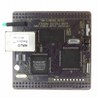
EZ80F920120MOD Zilog, EZ80F920120MOD Datasheet - Page 46

EZ80F920120MOD
Manufacturer Part Number
EZ80F920120MOD
Description
MODULE EZ80F92 512K 20MHZ
Manufacturer
Zilog
Datasheets
1.EZ80F920120MOD.pdf
(269 pages)
2.EZ80F920120MOD.pdf
(4 pages)
3.EZ80F920120MOD.pdf
(2 pages)
Specifications of EZ80F920120MOD
Module/board Type
Development Module
Processor Series
EZ80F92x
Core
eZ80
Data Bus Width
8 bit
Program Memory Type
Flash
Program Memory Size
1 MB
Interface Type
Cable
Maximum Clock Frequency
20 MHz
Operating Supply Voltage
0 V to 3.3 V
Maximum Operating Temperature
+ 70 C
Mounting Style
SMD/SMT
Package / Case
LQFP
Development Tools By Supplier
eZ80F920200ZCOG
Minimum Operating Temperature
0 C
For Use With/related Products
eZ80F92
Lead Free Status / RoHS Status
Contains lead / RoHS non-compliant
Other names
269-3157
EZ80F920120MOD
EZ80F920120MOD
- Current page: 46 of 269
- Download datasheet (4Mb)
Reset
PS015308-0404
Reset Operation
Power-On Reset
Note:
The Reset controller within the eZ80F92 device provides a consistent reset function for all
types of resets that can affect the system. A system reset, referred to in this document as
RESET, returns the eZ80F92 device to a defined state. All internal registers affected by
RESET return to their default conditions. RESET configures the GPIO port pins as inputs
and clears the CPU’s Program Counter to
ing RESET.
The events that can cause a RESET are:
•
•
•
•
•
•
During a RESET, an internal RESET mode timer holds the system in RESET mode for
257 system clock (SCLK) cycles. The RESET mode timer begins incrementing on the
next rising edge of SCLK following deactivation of all RESET events.
A Power-On Reset (POR) occurs each time the supply voltage to the part rises from below
the voltage brown-out threshold to above the POR voltage threshold (V
bandgap-referenced voltage detector sends a continuous RESET signal to the Reset con-
troller until the supply voltage (V
above V
Reset controller (T
until the RESET mode timer expires. POR operation is illustrated in Figure 3. The signals
in this figure are not drawn to scale and are for illustration purposes only.
Power-On Reset (POR)
Low-Voltage Brown-Out (VBO)
External RESET pin assertion
Watch-Dog Timer (WDT) time-out when configured to generate a RESET
Real-Time Clock alarm with the CPU in low-power SLEEP mode
Execution of a debug reset command
The user must determine if 257 SCLK cycles provides sufficient time for the pri-
mary crystal oscillator to stabilize.
POR
, an on-chip analog delay element briefly maintains the RESET signal to the
ANA
). After this analog delay, the eZ80F92 device is in RESET mode
P R E L I M I N A R Y
CC
) exceeds the POR voltage threshold. After V
000000h
. Program code execution ceases dur-
Product Specification
eZ80F92/eZ80F93
POR
). The internal
CC
rises
Reset
34
Related parts for EZ80F920120MOD
Image
Part Number
Description
Manufacturer
Datasheet
Request
R

Part Number:
Description:
Communication Controllers, ZILOG INTELLIGENT PERIPHERAL CONTROLLER (ZIP)
Manufacturer:
Zilog, Inc.
Datasheet:

Part Number:
Description:
KIT DEV FOR Z8 ENCORE 16K TO 64K
Manufacturer:
Zilog
Datasheet:

Part Number:
Description:
KIT DEV Z8 ENCORE XP 28-PIN
Manufacturer:
Zilog
Datasheet:

Part Number:
Description:
DEV KIT FOR Z8 ENCORE 8K/4K
Manufacturer:
Zilog
Datasheet:

Part Number:
Description:
KIT DEV Z8 ENCORE XP 28-PIN
Manufacturer:
Zilog
Datasheet:

Part Number:
Description:
DEV KIT FOR Z8 ENCORE 4K TO 8K
Manufacturer:
Zilog
Datasheet:

Part Number:
Description:
CMOS Z8 microcontroller. ROM 16 Kbytes, RAM 256 bytes, speed 16 MHz, 32 lines I/O, 3.0V to 5.5V
Manufacturer:
Zilog, Inc.
Datasheet:

Part Number:
Description:
Low-cost microcontroller. 512 bytes ROM, 61 bytes RAM, 8 MHz
Manufacturer:
Zilog, Inc.
Datasheet:

Part Number:
Description:
Z8 4K OTP Microcontroller
Manufacturer:
Zilog, Inc.
Datasheet:

Part Number:
Description:
CMOS SUPER8 ROMLESS MCU
Manufacturer:
Zilog, Inc.
Datasheet:

Part Number:
Description:
SL1866 CMOSZ8 OTP Microcontroller
Manufacturer:
Zilog, Inc.
Datasheet:

Part Number:
Description:
SL1866 CMOSZ8 OTP Microcontroller
Manufacturer:
Zilog, Inc.
Datasheet:

Part Number:
Description:
OTP (KB) = 1, RAM = 125, Speed = 12, I/O = 14, 8-bit Timers = 2, Comm Interfaces Other Features = Por, LV Protect, Voltage = 4.5-5.5V
Manufacturer:
Zilog, Inc.
Datasheet:

Part Number:
Description:
Manufacturer:
Zilog, Inc.
Datasheet:


