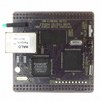
EZ80F920120MOD Zilog, EZ80F920120MOD Datasheet - Page 103

EZ80F920120MOD
Manufacturer Part Number
EZ80F920120MOD
Description
MODULE EZ80F92 512K 20MHZ
Manufacturer
Zilog
Datasheets
1.EZ80F920120MOD.pdf
(269 pages)
2.EZ80F920120MOD.pdf
(4 pages)
3.EZ80F920120MOD.pdf
(2 pages)
Specifications of EZ80F920120MOD
Module/board Type
Development Module
Processor Series
EZ80F92x
Core
eZ80
Data Bus Width
8 bit
Program Memory Type
Flash
Program Memory Size
1 MB
Interface Type
Cable
Maximum Clock Frequency
20 MHz
Operating Supply Voltage
0 V to 3.3 V
Maximum Operating Temperature
+ 70 C
Mounting Style
SMD/SMT
Package / Case
LQFP
Development Tools By Supplier
eZ80F920200ZCOG
Minimum Operating Temperature
0 C
For Use With/related Products
eZ80F92
Lead Free Status / RoHS Status
Contains lead / RoHS non-compliant
Other names
269-3157
EZ80F920120MOD
EZ80F920120MOD
- Current page: 103 of 269
- Download datasheet (4Mb)
PS015308-0404
Real-Time Clock Alarm
Real-Time Clock Oscillator and Source Selection
Real-Time Clock Battery Backup
Real-Time Clock Recommended Operation
The clock can be programmed to generate an alarm condition when the current count
matches the alarm set-point registers. Alarm registers are available for seconds, minutes,
hours, and day-of-the-week. Each alarm can be independently enabled. To generate an
alarm condition, the current time must match all enabled alarm values. For example, if the
day-of-the-week and hour alarms are both enabled, the alarm only occurs at the specified
hour on the specified day. The alarm triggers an interrupt if the interrupt enable bit,
INT_EN, is set. The alarm flag, ALARM, and corresponding interrupt to the CPU are
cleared by reading the RTC_CTRL register.
Alarm value registers and alarm control registers can be written at any time. Alarm condi-
tions are generated when the count value matches the alarm value. The comparison of
alarm and count values occurs whenever the RTC count increments (one time every sec-
ond). The RTC can also be forced to perform a comparison at any time by writing a 0 to
the RTC_UNLOCK bit (RTC_UNLOCK is not required to be changed to a 1 first).
The RTC count is driven by either the on-chip 32768 Hz crystal oscillator or a 50/60 Hz
power-line frequency input connected to the 32 KHz RTC_X
compensates for each of these options. The clock source and power-line frequencies are
selected in the RTC_CTRL register. Writing to the RTC_CTRL register resets the clock
divider.
The power supply pin (RTC_V
32 KHz oscillator is isolated from the other power supply pins on the eZ80F92 device. To
ensure that the RTC continues to keep time in the event of loss of line power to the appli-
cation, a battery can be used to supply power to the RTC and the oscillator via the
RTC_V
assembly.
Following a RESET from a powered-down condition, the counter values of the RTC are
undefined and all alarms are disabled. After a RESET from a powered-down condition, the
following procedure is recommended:
•
•
•
Write to RTC_CTRL to set RTC_UNLOCK and CLK_SEL
Write values to the RTC count registers to set the current time
Write values to the RTC alarm registers to set the appropriate alarm conditions
DD
pin. All V
SS
(ground) pins should be connected together on the printed circuit
P R E L I M I N A R Y
DD
) for the Real-Time Clock and associated low-power
OUT
Product Specification
pin. An internal divider
eZ80F92/eZ80F93
Real-Time Clock
91
Related parts for EZ80F920120MOD
Image
Part Number
Description
Manufacturer
Datasheet
Request
R

Part Number:
Description:
Communication Controllers, ZILOG INTELLIGENT PERIPHERAL CONTROLLER (ZIP)
Manufacturer:
Zilog, Inc.
Datasheet:

Part Number:
Description:
KIT DEV FOR Z8 ENCORE 16K TO 64K
Manufacturer:
Zilog
Datasheet:

Part Number:
Description:
KIT DEV Z8 ENCORE XP 28-PIN
Manufacturer:
Zilog
Datasheet:

Part Number:
Description:
DEV KIT FOR Z8 ENCORE 8K/4K
Manufacturer:
Zilog
Datasheet:

Part Number:
Description:
KIT DEV Z8 ENCORE XP 28-PIN
Manufacturer:
Zilog
Datasheet:

Part Number:
Description:
DEV KIT FOR Z8 ENCORE 4K TO 8K
Manufacturer:
Zilog
Datasheet:

Part Number:
Description:
CMOS Z8 microcontroller. ROM 16 Kbytes, RAM 256 bytes, speed 16 MHz, 32 lines I/O, 3.0V to 5.5V
Manufacturer:
Zilog, Inc.
Datasheet:

Part Number:
Description:
Low-cost microcontroller. 512 bytes ROM, 61 bytes RAM, 8 MHz
Manufacturer:
Zilog, Inc.
Datasheet:

Part Number:
Description:
Z8 4K OTP Microcontroller
Manufacturer:
Zilog, Inc.
Datasheet:

Part Number:
Description:
CMOS SUPER8 ROMLESS MCU
Manufacturer:
Zilog, Inc.
Datasheet:

Part Number:
Description:
SL1866 CMOSZ8 OTP Microcontroller
Manufacturer:
Zilog, Inc.
Datasheet:

Part Number:
Description:
SL1866 CMOSZ8 OTP Microcontroller
Manufacturer:
Zilog, Inc.
Datasheet:

Part Number:
Description:
OTP (KB) = 1, RAM = 125, Speed = 12, I/O = 14, 8-bit Timers = 2, Comm Interfaces Other Features = Por, LV Protect, Voltage = 4.5-5.5V
Manufacturer:
Zilog, Inc.
Datasheet:

Part Number:
Description:
Manufacturer:
Zilog, Inc.
Datasheet:


