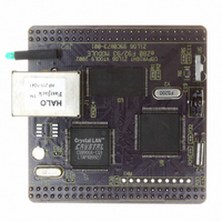
EZ80F920120MOD Zilog, EZ80F920120MOD Datasheet - Page 56

EZ80F920120MOD
Manufacturer Part Number
EZ80F920120MOD
Description
MODULE EZ80F92 512K 20MHZ
Manufacturer
Zilog
Datasheets
1.EZ80F920120MOD.pdf
(269 pages)
2.EZ80F920120MOD.pdf
(4 pages)
3.EZ80F920120MOD.pdf
(2 pages)
Specifications of EZ80F920120MOD
Module/board Type
Development Module
Processor Series
EZ80F92x
Core
eZ80
Data Bus Width
8 bit
Program Memory Type
Flash
Program Memory Size
1 MB
Interface Type
Cable
Maximum Clock Frequency
20 MHz
Operating Supply Voltage
0 V to 3.3 V
Maximum Operating Temperature
+ 70 C
Mounting Style
SMD/SMT
Package / Case
LQFP
Development Tools By Supplier
eZ80F920200ZCOG
Minimum Operating Temperature
0 C
For Use With/related Products
eZ80F92
Lead Free Status / RoHS Status
Contains lead / RoHS non-compliant
Other names
269-3157
EZ80F920120MOD
EZ80F920120MOD
- Current page: 56 of 269
- Download datasheet (4Mb)
PS015308-0404
GPIO Interrupts
Figure 5.GPIO Port Pin Block Diagram
Each port pin can be used as an interrupt source. Interrupts can be either level- or edge-
triggered.
Level-Triggered Interrupts
When the port is configured for level-triggered interrupts, the corresponding port pin is
tristated. An interrupt request is generated when the level at the pin is the same as the level
stored in the Port x Data register. The port pin value is sampled by the system clock. The
input pin must be held at the selected interrupt level for a minimum of 2 consecutive clock
cycles to initiate an interrupt. The interrupt request remains active as long as this condition
is maintained at the external source.
For example, if PD3 is programmed for low-level interrupt and the pin is forced Low for 2
consecutive clock cycles, an interrupt request signal is generated from that port pin and
sent to the CPU. The interrupt request signal remains active until the external device driv-
ing PD3 forces the pin High.
Edge-Triggered Interrupts
When the port is configured for edge-triggered interrupts, the corresponding port pin is
tristated. If the pin receives the correct edge from an external device, the port pin generates
an interrupt request signal to the CPU. Any time a port pin is configured for edge-triggered
System Clock
Data Bus
GPIO Register
Data (Output)
D
System Clock
Q
Mode 1
Mode 4
Mode 1
Mode 3
P R E L I M I N A R Y
GPIO Register
Data (Input)
Q
D
Q
D
General-Purpose Input/Output
GND
Product Specification
V
DD
eZ80F92/eZ80F93
Port
Pin
44
Related parts for EZ80F920120MOD
Image
Part Number
Description
Manufacturer
Datasheet
Request
R

Part Number:
Description:
Communication Controllers, ZILOG INTELLIGENT PERIPHERAL CONTROLLER (ZIP)
Manufacturer:
Zilog, Inc.
Datasheet:

Part Number:
Description:
KIT DEV FOR Z8 ENCORE 16K TO 64K
Manufacturer:
Zilog
Datasheet:

Part Number:
Description:
KIT DEV Z8 ENCORE XP 28-PIN
Manufacturer:
Zilog
Datasheet:

Part Number:
Description:
DEV KIT FOR Z8 ENCORE 8K/4K
Manufacturer:
Zilog
Datasheet:

Part Number:
Description:
KIT DEV Z8 ENCORE XP 28-PIN
Manufacturer:
Zilog
Datasheet:

Part Number:
Description:
DEV KIT FOR Z8 ENCORE 4K TO 8K
Manufacturer:
Zilog
Datasheet:

Part Number:
Description:
CMOS Z8 microcontroller. ROM 16 Kbytes, RAM 256 bytes, speed 16 MHz, 32 lines I/O, 3.0V to 5.5V
Manufacturer:
Zilog, Inc.
Datasheet:

Part Number:
Description:
Low-cost microcontroller. 512 bytes ROM, 61 bytes RAM, 8 MHz
Manufacturer:
Zilog, Inc.
Datasheet:

Part Number:
Description:
Z8 4K OTP Microcontroller
Manufacturer:
Zilog, Inc.
Datasheet:

Part Number:
Description:
CMOS SUPER8 ROMLESS MCU
Manufacturer:
Zilog, Inc.
Datasheet:

Part Number:
Description:
SL1866 CMOSZ8 OTP Microcontroller
Manufacturer:
Zilog, Inc.
Datasheet:

Part Number:
Description:
SL1866 CMOSZ8 OTP Microcontroller
Manufacturer:
Zilog, Inc.
Datasheet:

Part Number:
Description:
OTP (KB) = 1, RAM = 125, Speed = 12, I/O = 14, 8-bit Timers = 2, Comm Interfaces Other Features = Por, LV Protect, Voltage = 4.5-5.5V
Manufacturer:
Zilog, Inc.
Datasheet:

Part Number:
Description:
Manufacturer:
Zilog, Inc.
Datasheet:


