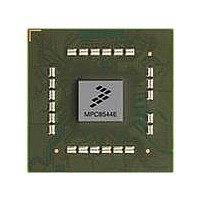
MPC8544DS Freescale Semiconductor, MPC8544DS Datasheet - Page 175

MPC8544DS
Manufacturer Part Number
MPC8544DS
Description
BOARD DEVELOPMENT SYSTEM 8544
Manufacturer
Freescale Semiconductor
Series
PowerQUICC III™r
Type
MPUr
Datasheets
1.MPC8544VTALF.pdf
(117 pages)
2.MPC8544VTALF.pdf
(2 pages)
3.MPC8544VTALF.pdf
(1340 pages)
4.MPC8544DS.pdf
(2 pages)
Specifications of MPC8544DS
Contents
Board
Processor To Be Evaluated
MPC8544E
Data Bus Width
32 bit
Interface Type
Ethernet, I2C
Operating Supply Voltage
- 0.3 V to + 1.1 V
Leaded Process Compatible
Yes
Peak Reflow Compatible (260 C)
Yes
Rohs Compliant
Yes
For Use With/related Products
MPC8544
For Use With
PPC8544EVTANG - EVAL MPC8544 783FCPBGA
Lead Free Status / RoHS Status
Lead free / RoHS Compliant
- MPC8544VTALF PDF datasheet
- MPC8544VTALF PDF datasheet #2
- MPC8544VTALF PDF datasheet #3
- MPC8544DS PDF datasheet #4
- Current page: 175 of 1340
- Download datasheet (12Mb)
4.4.3.8
The boot sequencer configuration options, shown in
configuration data from the serial ROM located on the I
MPC8544E. These options also specify normal or extended I
“Boot Sequencer Mode,”
Note that the values latched on these signals during POR are accessible through the memory-mapped
PORBMSR (POR boot mode status register) described in
Register (PORBMSR).”
Freescale Semiconductor
LGPL3/LSDCAS,
Functional
Default (1)
Default (11)
Functional
Signal
LA27
Signal
LGPL5
Boot Sequencer Configuration
MPC8544E PowerQUICC III Integrated Host Processor Family Reference Manual, Rev. 1
Reset Configuration
When the boot sequencer is enabled, the processor core will be held in reset
and thus prevented from fetching boot code until the boot sequencer has
completed its task, regardless of the state of the CPU boot configuration
signal described in
Reset Configuration
cfg_cpu_boot
cfg_boot_seq[0:1]
Name
Name
for more information on the boot sequencer.
Table 4-16. Boot Sequencer Configuration
Section 4.4.3.7, “CPU Boot
Table 4-15. CPU Boot Configuration
(Binary)
Value
(Binary)
Value
0
1
00
01
10
11
CPU boot holdoff mode. The e500 core is prevented from booting until
configured by an external master.
The e500 core is allowed to boot without waiting for configuration by an
external master (default).
Reserved
Normal I
loads configuration information from a ROM on the I
ROM must be present.
Extended I
loads configuration information from a ROM on the I
ROM must be present.
Boot sequencer is disabled. No I
NOTE
2
Table
C addressing mode is used. Boot sequencer is enabled and
2
C addressing mode is used. Boot sequencer is enabled and
2
C1 port before the host tries to configure the
Section 19.4.1.2, “POR Boot Mode Status
4-16, allow the boot sequencer to load
2
C addressing modes. See
Configuration.”
Meaning
Meaning
2
C ROM is accessed (default).
Reset, Clocking, and Initialization
2
Section 11.4.5,
2
C1 interface. A valid
C interface. A valid
4-17
Related parts for MPC8544DS
Image
Part Number
Description
Manufacturer
Datasheet
Request
R
Part Number:
Description:
Manufacturer:
Freescale Semiconductor, Inc
Datasheet:
Part Number:
Description:
Manufacturer:
Freescale Semiconductor, Inc
Datasheet:
Part Number:
Description:
Manufacturer:
Freescale Semiconductor, Inc
Datasheet:
Part Number:
Description:
Manufacturer:
Freescale Semiconductor, Inc
Datasheet:
Part Number:
Description:
Manufacturer:
Freescale Semiconductor, Inc
Datasheet:
Part Number:
Description:
Manufacturer:
Freescale Semiconductor, Inc
Datasheet:
Part Number:
Description:
Manufacturer:
Freescale Semiconductor, Inc
Datasheet:
Part Number:
Description:
Manufacturer:
Freescale Semiconductor, Inc
Datasheet:
Part Number:
Description:
Manufacturer:
Freescale Semiconductor, Inc
Datasheet:
Part Number:
Description:
Manufacturer:
Freescale Semiconductor, Inc
Datasheet:
Part Number:
Description:
Manufacturer:
Freescale Semiconductor, Inc
Datasheet:
Part Number:
Description:
Manufacturer:
Freescale Semiconductor, Inc
Datasheet:
Part Number:
Description:
Manufacturer:
Freescale Semiconductor, Inc
Datasheet:
Part Number:
Description:
Manufacturer:
Freescale Semiconductor, Inc
Datasheet:
Part Number:
Description:
Manufacturer:
Freescale Semiconductor, Inc
Datasheet:


