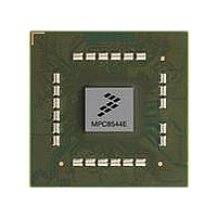
MPC8544DS Freescale Semiconductor, MPC8544DS Datasheet - Page 1020

MPC8544DS
Manufacturer Part Number
MPC8544DS
Description
BOARD DEVELOPMENT SYSTEM 8544
Manufacturer
Freescale Semiconductor
Series
PowerQUICC III™r
Type
MPUr
Datasheets
1.MPC8544VTALF.pdf
(117 pages)
2.MPC8544VTALF.pdf
(2 pages)
3.MPC8544VTALF.pdf
(1340 pages)
4.MPC8544DS.pdf
(2 pages)
Specifications of MPC8544DS
Contents
Board
Processor To Be Evaluated
MPC8544E
Data Bus Width
32 bit
Interface Type
Ethernet, I2C
Operating Supply Voltage
- 0.3 V to + 1.1 V
Leaded Process Compatible
Yes
Peak Reflow Compatible (260 C)
Yes
Rohs Compliant
Yes
For Use With/related Products
MPC8544
For Use With
PPC8544EVTANG - EVAL MPC8544 783FCPBGA
Lead Free Status / RoHS Status
Lead free / RoHS Compliant
- MPC8544VTALF PDF datasheet
- MPC8544VTALF PDF datasheet #2
- MPC8544VTALF PDF datasheet #3
- MPC8544DS PDF datasheet #4
- Current page: 1020 of 1340
- Download datasheet (12Mb)
PCI Bus Interface
17.3.2.10 PCI Bus Latency Timer Register—0x0D
Table 17-33
17.3.2.11 PCI Base Address Registers
A PCI base address register points to the beginnings of each address range to which the device responds
by asserting PCI_DEVSEL. The base address register (BAR) at offset 0x10 is a fixed 1-Mbyte window
that is automatically translated to the local configuration, control, and status registers address space.
The other base address registers are aliases (with differing format) of the PCI inbound ATMU windows;
see
corresponds to inbound ATMU window 1; the 64-bit base address registers at offsets 0x18 and 0x20
correspond to inbound ATMU windows 2 and 3. If one of these registers is written, the corresponding
ATMU register is also updated; if a PCI inbound ATMU register is written, the corresponding BAR is also
updated. If one of these registers is read, the corresponding size of ATMU is returned on the PCI bus
providing valid window size in the Inbound ATMU window attributes register.
Note that PCSRBAR cannot be updated through the inbound ATMU registers.
17-36
Offset 0x0D
Reset
Section 17.3.1.3, “PCI ATMU Inbound Registers.”
W
Bits
Bits
7–3 Latency Timer The maximum number of PCI clocks that the device, when mastering a transaction, holds the bus
2–0 Latency Timer Read-only bits. The minimum latency timer value when set is 8 PCI clocks.
7–0
R
Cache
Name
Size
Line
Name
7
describes the PCI latency timer register (PLTR).
MPC8544E PowerQUICC III Integrated Host Processor Family Reference Manual, Rev. 1
Represents the cache line size of the processor in terms of 32-bit words (8 32-bit words = 32 bytes).
PCLSR is read-write; however, for PCI operation an attempt to program this register to any value other
than 0x8 results in clearing it.
Table 17-32. PCI Bus Cache Line Size Register Field Descriptions
after PCI bus grant has been negated The value is in PCI clocks. The PCI 2.2 specification gives
rules by which the PCI bus interface unit completes transactions when the timer has expired.
Table 17-33. PCI Bus Latency Timer Register Field Descriptions
Figure 17-34. PCI Bus Latency Timer Register
Latency Timer
All zeros
Description
The 32-bit base address register at offset 0x14
Description
3
2
Latency Timer
Freescale Semiconductor
Access: Mixed
0
Related parts for MPC8544DS
Image
Part Number
Description
Manufacturer
Datasheet
Request
R
Part Number:
Description:
Manufacturer:
Freescale Semiconductor, Inc
Datasheet:
Part Number:
Description:
Manufacturer:
Freescale Semiconductor, Inc
Datasheet:
Part Number:
Description:
Manufacturer:
Freescale Semiconductor, Inc
Datasheet:
Part Number:
Description:
Manufacturer:
Freescale Semiconductor, Inc
Datasheet:
Part Number:
Description:
Manufacturer:
Freescale Semiconductor, Inc
Datasheet:
Part Number:
Description:
Manufacturer:
Freescale Semiconductor, Inc
Datasheet:
Part Number:
Description:
Manufacturer:
Freescale Semiconductor, Inc
Datasheet:
Part Number:
Description:
Manufacturer:
Freescale Semiconductor, Inc
Datasheet:
Part Number:
Description:
Manufacturer:
Freescale Semiconductor, Inc
Datasheet:
Part Number:
Description:
Manufacturer:
Freescale Semiconductor, Inc
Datasheet:
Part Number:
Description:
Manufacturer:
Freescale Semiconductor, Inc
Datasheet:
Part Number:
Description:
Manufacturer:
Freescale Semiconductor, Inc
Datasheet:
Part Number:
Description:
Manufacturer:
Freescale Semiconductor, Inc
Datasheet:
Part Number:
Description:
Manufacturer:
Freescale Semiconductor, Inc
Datasheet:
Part Number:
Description:
Manufacturer:
Freescale Semiconductor, Inc
Datasheet:


