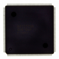
D6417729RHF200BV Renesas Electronics America, D6417729RHF200BV Datasheet - Page 747

D6417729RHF200BV
Manufacturer Part Number
D6417729RHF200BV
Description
IC SUPER H MPU ROMLESS 208QFP
Manufacturer
Renesas Electronics America
Series
SuperH® SH7700r
Datasheet
1.D6417729RF133BV.pdf
(857 pages)
Specifications of D6417729RHF200BV
Core Processor
SH-3 DSP
Core Size
32-Bit
Speed
200MHz
Connectivity
EBI/EMI, FIFO, IrDA, SCI, SmartCard
Peripherals
DMA, POR, WDT
Number Of I /o
96
Program Memory Type
ROMless
Ram Size
32K x 8
Voltage - Supply (vcc/vdd)
1.85 V ~ 2.15 V
Data Converters
A/D 8x10b; D/A 2x8b
Oscillator Type
Internal
Operating Temperature
-20°C ~ 75°C
Package / Case
208-QFP Exposed Pad, 208-eQFP, 208-HQFP
Lead Free Status / RoHS Status
Lead free / RoHS Compliant
Eeprom Size
-
Program Memory Size
-
Available stocks
Company
Part Number
Manufacturer
Quantity
Price
Company:
Part Number:
D6417729RHF200BV
Manufacturer:
EVERLIGHT
Quantity:
1 000
Company:
Part Number:
D6417729RHF200BV
Manufacturer:
Renesas Electronics America
Quantity:
10 000
- Current page: 747 of 857
- Download datasheet (5Mb)
Data loaded into the output pin boundary scan register in the Capture-DR state is not used for
external circuit testing (it is replaced by a shift operation).
The instruction code is 0000.
23.5.2
1. Boundary scan mode covers clock-related signals (EXTAL, EXTAL2, XTAL, XTAL2,
2. Boundary scan mode does not cover reset-related signals (RESETP, RESETM, CA).
3. Boundary scan mode does not cover UDI-related signals (TCK, TDI, TDO, TMS, TRST).
4. When a boundary scan test is carried out, ensure that the CKIO clock operates constantly.
5. Fix the RESETP pin low.
6. Fix the CA pin high, and the ASEMD0 pin low.
23.6
1. An UDI command other than an UDI interrupt, once set, will not be modified as long as
2. Because chip operations are suspended in standby mode, UDI commands are not accepted.
3. The UDI is used for emulator connection. Therefore, UDI functions cannot be used when
23.7
The AUD is a function exclusively for use by an emulator. Refer to the User's Manual for the
relevant emulator for details of the AUD.
CKIO).
The CKIO frequency range is as follows:
Minimum: 1 MHz
Maximum: Maximum frequency for respective clock mode specified in the CPG section
Set pins MD[2:0] to the clock mode to be used.
After powering on, wait for the CKIO clock to stabilize before performing a boundary scan
test.
another command is not re-issued from the UDI. An UDI interrupt command, however, will
be changed to a bypass command once set.
However, the TAP controller remains in operation at this time.
using an emulator.
Points for Attention
Usage Notes
Advanced User Debugger (AUD)
Rev. 5.0, 09/03, page 699 of 806
Related parts for D6417729RHF200BV
Image
Part Number
Description
Manufacturer
Datasheet
Request
R

Part Number:
Description:
KIT STARTER FOR M16C/29
Manufacturer:
Renesas Electronics America
Datasheet:

Part Number:
Description:
KIT STARTER FOR R8C/2D
Manufacturer:
Renesas Electronics America
Datasheet:

Part Number:
Description:
R0K33062P STARTER KIT
Manufacturer:
Renesas Electronics America
Datasheet:

Part Number:
Description:
KIT STARTER FOR R8C/23 E8A
Manufacturer:
Renesas Electronics America
Datasheet:

Part Number:
Description:
KIT STARTER FOR R8C/25
Manufacturer:
Renesas Electronics America
Datasheet:

Part Number:
Description:
KIT STARTER H8S2456 SHARPE DSPLY
Manufacturer:
Renesas Electronics America
Datasheet:

Part Number:
Description:
KIT STARTER FOR R8C38C
Manufacturer:
Renesas Electronics America
Datasheet:

Part Number:
Description:
KIT STARTER FOR R8C35C
Manufacturer:
Renesas Electronics America
Datasheet:

Part Number:
Description:
KIT STARTER FOR R8CL3AC+LCD APPS
Manufacturer:
Renesas Electronics America
Datasheet:

Part Number:
Description:
KIT STARTER FOR RX610
Manufacturer:
Renesas Electronics America
Datasheet:

Part Number:
Description:
KIT STARTER FOR R32C/118
Manufacturer:
Renesas Electronics America
Datasheet:

Part Number:
Description:
KIT DEV RSK-R8C/26-29
Manufacturer:
Renesas Electronics America
Datasheet:

Part Number:
Description:
KIT STARTER FOR SH7124
Manufacturer:
Renesas Electronics America
Datasheet:

Part Number:
Description:
KIT STARTER FOR H8SX/1622
Manufacturer:
Renesas Electronics America
Datasheet:

Part Number:
Description:
KIT DEV FOR SH7203
Manufacturer:
Renesas Electronics America
Datasheet:


