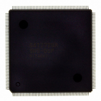
D6417729RHF200BV Renesas Electronics America, D6417729RHF200BV Datasheet - Page 40

D6417729RHF200BV
Manufacturer Part Number
D6417729RHF200BV
Description
IC SUPER H MPU ROMLESS 208QFP
Manufacturer
Renesas Electronics America
Series
SuperH® SH7700r
Datasheet
1.D6417729RF133BV.pdf
(857 pages)
Specifications of D6417729RHF200BV
Core Processor
SH-3 DSP
Core Size
32-Bit
Speed
200MHz
Connectivity
EBI/EMI, FIFO, IrDA, SCI, SmartCard
Peripherals
DMA, POR, WDT
Number Of I /o
96
Program Memory Type
ROMless
Ram Size
32K x 8
Voltage - Supply (vcc/vdd)
1.85 V ~ 2.15 V
Data Converters
A/D 8x10b; D/A 2x8b
Oscillator Type
Internal
Operating Temperature
-20°C ~ 75°C
Package / Case
208-QFP Exposed Pad, 208-eQFP, 208-HQFP
Lead Free Status / RoHS Status
Lead free / RoHS Compliant
Eeprom Size
-
Program Memory Size
-
Available stocks
Company
Part Number
Manufacturer
Quantity
Price
Company:
Part Number:
D6417729RHF200BV
Manufacturer:
EVERLIGHT
Quantity:
1 000
Company:
Part Number:
D6417729RHF200BV
Manufacturer:
Renesas Electronics America
Quantity:
10 000
- Current page: 40 of 857
- Download datasheet (5Mb)
Figure 17.8
Figure 17.9
Figure 17.10 Sample Flowchart for Receiving Serial Data (cont)............................................. 591
Figure 17.11 Example of SCIF Receive Operation (8-Bit Data, Parity, One Stop Bit)............. 593
Figure 17.12 Example of Operation Using Modem Control (RTS)........................................... 593
Figure 17.13 Receive Data Sampling Timing in Asynchronous Mode ..................................... 596
Figure 18.1
Figure 18.2
Figure 18.3
Figure 18.4
Figure 18.5
Figure 20.1
Figure 20.2
Figure 20.3
Figure 20.4
Figure 20.5
Figure 20.6
Figure 20.7
Figure 20.8
Figure 20.9
Figure 20.10 Port K ................................................................................................................... 649
Figure 20.11 Port L.................................................................................................................... 651
Figure 20.12 SC Port ................................................................................................................. 653
Figure 21.1
Figure 21.2
Figure 21.3
Figure 21.4
Figure 21.5
Figure 21.6
Figure 21.7
Figure 21.8
Figure 21.9
Figure 21.10 Analog Input Pin Equivalent Circuit .................................................................... 676
Figure 22.1
Figure 22.2
Figure 23.1
Figure 23.2
Figure 23.3
Figure 24.1
Figure 24.2
Figure 24.3
Rev. 5.0, 09/03, page xxxviii of xlvi
Example of Operation Using Modem Control (CTS)........................................... 588
Sample Flowchart for Receiving Serial Data ....................................................... 590
Block Diagram of IrDA........................................................................................ 600
SCPT[3]/SCK1 Pin .............................................................................................. 601
SCPT[2]/TxD1 Pin............................................................................................... 602
SCPT[2]/RxD1 Pin............................................................................................... 603
Transmit/Receive Operation................................................................................. 608
Port A ................................................................................................................... 631
Port B ................................................................................................................... 633
Port C ................................................................................................................... 635
Port D ................................................................................................................... 637
Port E.................................................................................................................... 639
Port F.................................................................................................................... 641
Port G ................................................................................................................... 643
Port H ................................................................................................................... 645
Port J .................................................................................................................... 647
Block Diagram of A/D Converter ........................................................................ 658
A/D Data Register Access Operation (Reading H'AA40).................................... 665
Example of A/D Converter Operation (Single Mode, Channel 1 Selected) ......... 667
Example of A/D Converter Operation (Multi Mode, Channels AN0 to AN2
Selected) ............................................................................................................... 669
Example of A/D Converter Operation (Scan Mode, Channels AN0 to AN2
Selected) ............................................................................................................... 671
A/D Conversion Timing ....................................................................................... 672
External Trigger Input Timing ............................................................................. 673
Definitions of A/D Conversion Accuracy ............................................................ 675
Example of Analog Input Protection Circuit ........................................................ 676
Block Diagram of D/A Converter ........................................................................ 679
Example of D/A Converter Operation.................................................................. 683
Block Diagram of UDI ......................................................................................... 686
TAP Controller State Transitions ......................................................................... 695
UDI Reset............................................................................................................. 697
EXTAL Clock Input Timing ................................................................................ 708
CKIO Clock Input Timing ................................................................................... 708
CKIO Clock Output Timing................................................................................. 708
Related parts for D6417729RHF200BV
Image
Part Number
Description
Manufacturer
Datasheet
Request
R

Part Number:
Description:
KIT STARTER FOR M16C/29
Manufacturer:
Renesas Electronics America
Datasheet:

Part Number:
Description:
KIT STARTER FOR R8C/2D
Manufacturer:
Renesas Electronics America
Datasheet:

Part Number:
Description:
R0K33062P STARTER KIT
Manufacturer:
Renesas Electronics America
Datasheet:

Part Number:
Description:
KIT STARTER FOR R8C/23 E8A
Manufacturer:
Renesas Electronics America
Datasheet:

Part Number:
Description:
KIT STARTER FOR R8C/25
Manufacturer:
Renesas Electronics America
Datasheet:

Part Number:
Description:
KIT STARTER H8S2456 SHARPE DSPLY
Manufacturer:
Renesas Electronics America
Datasheet:

Part Number:
Description:
KIT STARTER FOR R8C38C
Manufacturer:
Renesas Electronics America
Datasheet:

Part Number:
Description:
KIT STARTER FOR R8C35C
Manufacturer:
Renesas Electronics America
Datasheet:

Part Number:
Description:
KIT STARTER FOR R8CL3AC+LCD APPS
Manufacturer:
Renesas Electronics America
Datasheet:

Part Number:
Description:
KIT STARTER FOR RX610
Manufacturer:
Renesas Electronics America
Datasheet:

Part Number:
Description:
KIT STARTER FOR R32C/118
Manufacturer:
Renesas Electronics America
Datasheet:

Part Number:
Description:
KIT DEV RSK-R8C/26-29
Manufacturer:
Renesas Electronics America
Datasheet:

Part Number:
Description:
KIT STARTER FOR SH7124
Manufacturer:
Renesas Electronics America
Datasheet:

Part Number:
Description:
KIT STARTER FOR H8SX/1622
Manufacturer:
Renesas Electronics America
Datasheet:

Part Number:
Description:
KIT DEV FOR SH7203
Manufacturer:
Renesas Electronics America
Datasheet:


