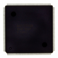
D6417729RHF200BV Renesas Electronics America, D6417729RHF200BV Datasheet - Page 38

D6417729RHF200BV
Manufacturer Part Number
D6417729RHF200BV
Description
IC SUPER H MPU ROMLESS 208QFP
Manufacturer
Renesas Electronics America
Series
SuperH® SH7700r
Datasheet
1.D6417729RF133BV.pdf
(857 pages)
Specifications of D6417729RHF200BV
Core Processor
SH-3 DSP
Core Size
32-Bit
Speed
200MHz
Connectivity
EBI/EMI, FIFO, IrDA, SCI, SmartCard
Peripherals
DMA, POR, WDT
Number Of I /o
96
Program Memory Type
ROMless
Ram Size
32K x 8
Voltage - Supply (vcc/vdd)
1.85 V ~ 2.15 V
Data Converters
A/D 8x10b; D/A 2x8b
Oscillator Type
Internal
Operating Temperature
-20°C ~ 75°C
Package / Case
208-QFP Exposed Pad, 208-eQFP, 208-HQFP
Lead Free Status / RoHS Status
Lead free / RoHS Compliant
Eeprom Size
-
Program Memory Size
-
Available stocks
Company
Part Number
Manufacturer
Quantity
Price
Company:
Part Number:
D6417729RHF200BV
Manufacturer:
EVERLIGHT
Quantity:
1 000
Company:
Part Number:
D6417729RHF200BV
Manufacturer:
Renesas Electronics America
Quantity:
10 000
- Current page: 38 of 857
- Download datasheet (5Mb)
Figure 12.10 Example of Transfer Timing in the Indirect Address Mode in Dual Address
Figure 12.11 Data Flow in Single Address Mode...................................................................... 401
Figure 12.12 Example of DMA Transfer Timing in Single Address Mode .............................. 402
Figure 12.13 Example of DMA Transfer Timing in Single Address Mode (External Memory3
Figure 12.14 Example of Transfer in Cycle-Steal Mode ........................................................... 403
Figure 12.15 Example of Transfer in Burst Mode ..................................................................... 404
Figure 12.16 Bus State when Multiple Channels Are Operating............................................... 406
Figure 12.17 Cycle-Steal Mode, Level Input (CPU Access: 2 Cycles) ..................................... 409
Figure 12.18 Cycle-Steal Mode, Level Input (CPU Access: 3 Cycles) ..................................... 410
Figure 12.19 Cycle-Steal Mode, Level input (CPU Access: 2 Cycles,
Figure 12.20 Cycle-Steal Mode, Level input (CPU Access: 2 Cycles, DREQ Input Delayed) . 412
Figure 12.21 Cycle-Steal Mode, Edge input (CPU Access: 2 Cycles) ...................................... 413
Figure 12.22 Burst Mode, Level Input ...................................................................................... 414
Figure 12.23 Burst Mode, Edge Input ....................................................................................... 415
Figure 12.24 Source Address Reload Function Diagram........................................................... 416
Figure 12.25 Timing Chart of Source Address Reload Function............................................... 417
Figure 12.26 Block Diagram of CMT ....................................................................................... 420
Figure 12.27 Counter Operation ................................................................................................ 424
Figure 12.28 Count Timing ....................................................................................................... 425
Figure 12.29 CMF Setting Timing ............................................................................................ 426
Figure 12.30 Timing of CMF Clearing by the CPU .................................................................. 426
Figure 13.1
Figure 13.2
Figure 13.3
Figure 13.4
Figure 13.5
Figure 13.6
Figure 13.7
Figure 13.8
Figure 13.9
Figure 14.1
Figure 14.2
Figure 14.3
Figure 14.4
Figure 14.5
Figure 14.6
Figure 15.1
Figure 15.2
Figure 15.3
Rev. 5.0, 09/03, page xxxvi of xlvi
Mode .................................................................................................................... 400
Space (Ordinary Memory)
DMA RD Access: 4 Cycles)................................................................................. 411
Block Diagram of TMU ....................................................................................... 434
Setting the Count Operation ................................................................................. 445
Auto-Reload Count Operation.............................................................................. 446
Count Timing when Operating on Internal Clock ................................................ 446
Count Timing when Operating on External Clock (Both Edges Detected) .......... 447
Count Timing when Operating on On-Chip RTC Clock ...................................... 447
Operation Timing when Using Input Capture Function
(Using TCLK Rising Edge).................................................................................. 448
UNF Setting Timing............................................................................................. 448
Status Flag Clearing Timing................................................................................. 449
Block Diagram of RTC ........................................................................................ 452
Setting the Time ................................................................................................... 466
Reading the Time ................................................................................................. 467
Using the Alarm Function .................................................................................... 468
Example of Crystal Oscillator Circuit Connection............................................... 469
Using Periodic Interrupt Function ........................................................................ 470
Block Diagram of SCI .......................................................................................... 472
SCPT[1]/SCK0 Pin .............................................................................................. 473
SCPT[0]/TxD0 Pin............................................................................................... 474
External Device with DACK) .............................. 403
Related parts for D6417729RHF200BV
Image
Part Number
Description
Manufacturer
Datasheet
Request
R

Part Number:
Description:
KIT STARTER FOR M16C/29
Manufacturer:
Renesas Electronics America
Datasheet:

Part Number:
Description:
KIT STARTER FOR R8C/2D
Manufacturer:
Renesas Electronics America
Datasheet:

Part Number:
Description:
R0K33062P STARTER KIT
Manufacturer:
Renesas Electronics America
Datasheet:

Part Number:
Description:
KIT STARTER FOR R8C/23 E8A
Manufacturer:
Renesas Electronics America
Datasheet:

Part Number:
Description:
KIT STARTER FOR R8C/25
Manufacturer:
Renesas Electronics America
Datasheet:

Part Number:
Description:
KIT STARTER H8S2456 SHARPE DSPLY
Manufacturer:
Renesas Electronics America
Datasheet:

Part Number:
Description:
KIT STARTER FOR R8C38C
Manufacturer:
Renesas Electronics America
Datasheet:

Part Number:
Description:
KIT STARTER FOR R8C35C
Manufacturer:
Renesas Electronics America
Datasheet:

Part Number:
Description:
KIT STARTER FOR R8CL3AC+LCD APPS
Manufacturer:
Renesas Electronics America
Datasheet:

Part Number:
Description:
KIT STARTER FOR RX610
Manufacturer:
Renesas Electronics America
Datasheet:

Part Number:
Description:
KIT STARTER FOR R32C/118
Manufacturer:
Renesas Electronics America
Datasheet:

Part Number:
Description:
KIT DEV RSK-R8C/26-29
Manufacturer:
Renesas Electronics America
Datasheet:

Part Number:
Description:
KIT STARTER FOR SH7124
Manufacturer:
Renesas Electronics America
Datasheet:

Part Number:
Description:
KIT STARTER FOR H8SX/1622
Manufacturer:
Renesas Electronics America
Datasheet:

Part Number:
Description:
KIT DEV FOR SH7203
Manufacturer:
Renesas Electronics America
Datasheet:


