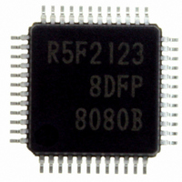
R5F21238DFP#U0 Renesas Electronics America, R5F21238DFP#U0 Datasheet - Page 537

R5F21238DFP#U0
Manufacturer Part Number
R5F21238DFP#U0
Description
IC R8C/23 MCU FLASH 48-LQFP
Manufacturer
Renesas Electronics America
Series
R8C/2x/23r
Specifications of R5F21238DFP#U0
Core Size
16/32-Bit
Program Memory Size
64KB (64K x 8)
Peripherals
POR, Voltage Detect, WDT
Core Processor
R8C
Speed
20MHz
Connectivity
CAN, I²C, LIN, SIO, SSU, UART/USART
Number Of I /o
41
Program Memory Type
FLASH
Ram Size
3K x 8
Voltage - Supply (vcc/vdd)
2.7 V ~ 5.5 V
Data Converters
A/D 12x10b
Oscillator Type
Internal
Operating Temperature
-40°C ~ 85°C
Package / Case
48-LQFP
No. Of I/o's
41
Ram Memory Size
3KB
Cpu Speed
20MHz
No. Of Timers
4
Digital Ic Case Style
LQFP
Embedded Interface Type
CAN, I2C, UART
Rohs Compliant
Yes
Cpu Family
R8C
Device Core Size
16b
Frequency (max)
20MHz
Interface Type
I2C/UART
Total Internal Ram Size
3KB
# I/os (max)
41
Number Of Timers - General Purpose
5
Operating Supply Voltage (typ)
3.3/5V
Operating Supply Voltage (max)
5.5V
Operating Supply Voltage (min)
3V
On-chip Adc
12-chx10-bit
Instruction Set Architecture
CISC
Operating Temp Range
-40C to 85C
Operating Temperature Classification
Industrial
Mounting
Surface Mount
Pin Count
48
Package Type
LQFP
Lead Free Status / RoHS Status
Lead free / RoHS Compliant
For Use With
RCDK8C - KIT DEV EVAL FOR CAN R8C/23R0K521237S000BE - KIT DEV RSK R8C/23R0E521237CPE00 - EMULATOR COMPACT R8C/20/21/22/23
Eeprom Size
-
Lead Free Status / Rohs Status
Compliant
Available stocks
Company
Part Number
Manufacturer
Quantity
Price
- Current page: 537 of 551
- Download datasheet (6Mb)
Rev.
1.00
REVISION HISTORY
Oct 27, 2006
Date
Page
103
111
75
76
77
79
80
84
85
86
87
88
89
90
91
92
93
94
Figure 10.4 OCD Register;
Figure 10.5 Registers FRA0 and FRA1;
Figure 10.6 FRA2 Register;
Figure 10.7 VCA2 Register;
Figure 10.9 Examples of XIN Clock Connection Circuit;
10.2.2 High-Speed On-Chip Oscillator Clock;
On the 4th line revised.
On the2nd line from the bottom; “Adjust the amount of high-speed on-chip
oscillator frequency to 40 MHz and below by setting the FRA1 register.” added.
10.4.1.3 Low-Speed On-Chip Oscillator Mode;
mode, setting the VCA20 bit in the VCA2 register to 1 (internal power low
consumption enabled) enables lower consumption current in wait mode.” added.
10.4.2.4 Exiting Wait Mode;
to Interrupt Routine Execution. added.
Figure 10.10 Time from Wait Mode to Interrupt Routine Execution revised.
10.4.2.5 Reducing Internal Power Consumption and Figure 10.11 Procedure for
Enabling Reduced Internal Power Consumption Using VCA20 bit added
10.4.3.3 Exiting Stop Mode, on the 4th line;
Figure 10.12 Time from Stop Mode to Interrupt Routine Execution added.
“Figure 10.11 State Transitions in Power Control Mode” →
“Figure 10.13 State Transitions in Power Control Mode” corrected.
10.5.1 How to Use Oscillation Stop Detection Function, on the 6th line;
“Figure 10.12 ~” → “Figure 10.14 ~” corrected.
“Figure 10.13 ~” → “Figure 10.15 ~” corrected.
“10.6. Notes on Clock Generation Circuit” revised.
Figure 12.5 Registers INT0IC to INT3IC;
Figure 12.13 INTF Register revised
NOTE7; “Figure 10.12” → “Figure 10.14”corrected.
High-Speed On-Chip Oscillator Control Register 0
High-Speed On-Chip Oscillator Control Register 1
High-Speed On-Chip Oscillator Control Register 2
NOTE3 added.
Voltage Detection Register 2
NOTE5 added.
Ceramic resonator external circuit revised.
On the 2nd line from the bottom; “To enter wait mode from low-speed clock
On the 13th line from the bottom; Figure 10.10 shows the Time from Wait Mode
“Figure 10.12 shows the Time from Stop Mode to Interrupt Routine Execution.”
“Figure 10.13” → “Figure 10.15” corrected.
On the 10th line; “Figure 10.12” → “Figure 10.14” corrected.
NOTE3; “INTOPL” → “INTiPL” corrected.
R8C/22 Group, R8C/23 Group Hardware Manual
added.
C - 14
Description
(1)
revised.
Summary
(1)
(1)
(1)
; NOTE2 revised.
; NOTE revised.
revised.
Related parts for R5F21238DFP#U0
Image
Part Number
Description
Manufacturer
Datasheet
Request
R

Part Number:
Description:
KIT STARTER FOR M16C/29
Manufacturer:
Renesas Electronics America
Datasheet:

Part Number:
Description:
KIT STARTER FOR R8C/2D
Manufacturer:
Renesas Electronics America
Datasheet:

Part Number:
Description:
R0K33062P STARTER KIT
Manufacturer:
Renesas Electronics America
Datasheet:

Part Number:
Description:
KIT STARTER FOR R8C/23 E8A
Manufacturer:
Renesas Electronics America
Datasheet:

Part Number:
Description:
KIT STARTER FOR R8C/25
Manufacturer:
Renesas Electronics America
Datasheet:

Part Number:
Description:
KIT STARTER H8S2456 SHARPE DSPLY
Manufacturer:
Renesas Electronics America
Datasheet:

Part Number:
Description:
KIT STARTER FOR R8C38C
Manufacturer:
Renesas Electronics America
Datasheet:

Part Number:
Description:
KIT STARTER FOR R8C35C
Manufacturer:
Renesas Electronics America
Datasheet:

Part Number:
Description:
KIT STARTER FOR R8CL3AC+LCD APPS
Manufacturer:
Renesas Electronics America
Datasheet:

Part Number:
Description:
KIT STARTER FOR RX610
Manufacturer:
Renesas Electronics America
Datasheet:

Part Number:
Description:
KIT STARTER FOR R32C/118
Manufacturer:
Renesas Electronics America
Datasheet:

Part Number:
Description:
KIT DEV RSK-R8C/26-29
Manufacturer:
Renesas Electronics America
Datasheet:

Part Number:
Description:
KIT STARTER FOR SH7124
Manufacturer:
Renesas Electronics America
Datasheet:

Part Number:
Description:
KIT STARTER FOR H8SX/1622
Manufacturer:
Renesas Electronics America
Datasheet:

Part Number:
Description:
KIT DEV FOR SH7203
Manufacturer:
Renesas Electronics America
Datasheet:


