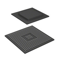
R8A77850ANBGV Renesas Electronics America, R8A77850ANBGV Datasheet - Page 239

R8A77850ANBGV
Manufacturer Part Number
R8A77850ANBGV
Description
IC SUPERH MPU ROMLESS 436-BGA
Manufacturer
Renesas Electronics America
Series
SuperH® SH7780r
Datasheet
1.R8A77850AADBGV.pdf
(1694 pages)
Specifications of R8A77850ANBGV
Core Processor
SH-4A
Core Size
32-Bit
Speed
600MHz
Connectivity
Audio Codec, MMC, Serial Sound, SCI, SIO, SPI, SSI
Peripherals
DMA, POR, WDT
Number Of I /o
108
Program Memory Type
ROMless
Ram Size
8K x 8
Voltage - Supply (vcc/vdd)
1 V ~ 1.2 V
Oscillator Type
External
Operating Temperature
-20°C ~ 75°C
Package / Case
436-BGA
Lead Free Status / RoHS Status
Lead free / RoHS Compliant
Eeprom Size
-
Program Memory Size
-
Data Converters
-
Available stocks
Company
Part Number
Manufacturer
Quantity
Price
Company:
Part Number:
R8A77850ANBGV
Manufacturer:
Renesas Electronics America
Quantity:
10 000
- Current page: 239 of 1694
- Download datasheet (9Mb)
7.9
The address mode of this LSI after a power-on reset or manual reset can be switched between 29-
bit address mode and 32-bit address extended mode by specifying external pins. The following
changes apply when this LSI is booted up in 32-bit address extended mode.
7.9.1
When 32-bit address extended mode is specified by external pins, the following initial entries are
recorded in the PMB after a power-on reset or manual reset, and the SE bit in the PASCR register
is initialized to 1. For entries 2 to 15, only the V bit is initialized to 0.
7.9.2
Immediately after a power-on or manual reset, the P1 or P2 area is mapped to the PMB. Therefore,
when an area other than that indicated by the initial entry needs to be mapped, follow the
procedures below to modify the PMB, taking care not to generate PMB misses and multiple PMB
hits. The procedure should be set up within the boot routine and should be executed before
activation of the caches and TLB (CCR.ICE = 1, CCR.OCE = 1, and MMUCR.AT = 1). Do not
use routines other than the boot routine to change the value recorded in the PMB.
(1)
1. Read the initial entry, change only the SZ bits to reduce the page size, and save the new value
2. Invalidate the entry remaining in the ITLB that corresponds to the PMB by writing 1 to the TI
3. In the memory-mapped PMB, record PMB entries to fill the P1 or P2 area in which the PMB
4. Execute one of the following steps, A, B, and C. Do not execute a branch or operand access for
Entry
0
1
over the previous entry. The program that changes the PMB should be allocated within 1
Mbyte of the top of the page with the reduced size.
bit in the MMUCR register.
translation information is evicted by step 1.
the P1 or P2 area in which the PMB translation information is evicted by step 1.
A. Perform a branch using the RTE instruction.
B. Execute the ICBI instruction for any address (including non-cacheable area).
When the Program Modifying the PMB is in the P1 or P2 Area
32-Bit Boot Function
Initial Entries to PMB
Notes on 32-Bit Boot
VPN[31:24] PPN[31:24]
10000000
10100000
00000000
00000000
V
1
1
SZ[1:0]
11
11
Rev.1.00 Jan. 10, 2008 Page 207 of 1658
7. Memory Management Unit (MMU)
C
1
0
UB
0
0
REJ09B0261-0100
WT
1
0
Related parts for R8A77850ANBGV
Image
Part Number
Description
Manufacturer
Datasheet
Request
R

Part Number:
Description:
KIT STARTER FOR M16C/29
Manufacturer:
Renesas Electronics America
Datasheet:

Part Number:
Description:
KIT STARTER FOR R8C/2D
Manufacturer:
Renesas Electronics America
Datasheet:

Part Number:
Description:
R0K33062P STARTER KIT
Manufacturer:
Renesas Electronics America
Datasheet:

Part Number:
Description:
KIT STARTER FOR R8C/23 E8A
Manufacturer:
Renesas Electronics America
Datasheet:

Part Number:
Description:
KIT STARTER FOR R8C/25
Manufacturer:
Renesas Electronics America
Datasheet:

Part Number:
Description:
KIT STARTER H8S2456 SHARPE DSPLY
Manufacturer:
Renesas Electronics America
Datasheet:

Part Number:
Description:
KIT STARTER FOR R8C38C
Manufacturer:
Renesas Electronics America
Datasheet:

Part Number:
Description:
KIT STARTER FOR R8C35C
Manufacturer:
Renesas Electronics America
Datasheet:

Part Number:
Description:
KIT STARTER FOR R8CL3AC+LCD APPS
Manufacturer:
Renesas Electronics America
Datasheet:

Part Number:
Description:
KIT STARTER FOR RX610
Manufacturer:
Renesas Electronics America
Datasheet:

Part Number:
Description:
KIT STARTER FOR R32C/118
Manufacturer:
Renesas Electronics America
Datasheet:

Part Number:
Description:
KIT DEV RSK-R8C/26-29
Manufacturer:
Renesas Electronics America
Datasheet:

Part Number:
Description:
KIT STARTER FOR SH7124
Manufacturer:
Renesas Electronics America
Datasheet:

Part Number:
Description:
KIT STARTER FOR H8SX/1622
Manufacturer:
Renesas Electronics America
Datasheet:

Part Number:
Description:
KIT DEV FOR SH7203
Manufacturer:
Renesas Electronics America
Datasheet:


