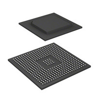
R8A77850ANBGV Renesas Electronics America, R8A77850ANBGV Datasheet - Page 1535

R8A77850ANBGV
Manufacturer Part Number
R8A77850ANBGV
Description
IC SUPERH MPU ROMLESS 436-BGA
Manufacturer
Renesas Electronics America
Series
SuperH® SH7780r
Datasheet
1.R8A77850AADBGV.pdf
(1694 pages)
Specifications of R8A77850ANBGV
Core Processor
SH-4A
Core Size
32-Bit
Speed
600MHz
Connectivity
Audio Codec, MMC, Serial Sound, SCI, SIO, SPI, SSI
Peripherals
DMA, POR, WDT
Number Of I /o
108
Program Memory Type
ROMless
Ram Size
8K x 8
Voltage - Supply (vcc/vdd)
1 V ~ 1.2 V
Oscillator Type
External
Operating Temperature
-20°C ~ 75°C
Package / Case
436-BGA
Lead Free Status / RoHS Status
Lead free / RoHS Compliant
Eeprom Size
-
Program Memory Size
-
Data Converters
-
Available stocks
Company
Part Number
Manufacturer
Quantity
Price
Company:
Part Number:
R8A77850ANBGV
Manufacturer:
Renesas Electronics America
Quantity:
10 000
- Current page: 1535 of 1694
- Download datasheet (9Mb)
30.4
30.4.1
In the H-UDI in this LSI, the boundary-scan TAP controller is separated from the TAP controller
for other H-UDI function control. When the TRST is asserted (including when the power is turned
on), the boundary-scan TAP controller operates and the boundary scan function specified in JTAG
can be used. By inputting the switching command, an H-UDI reset and H-UDI interrupts can be
used. However, the following restrictions are put on this LSI.
• Clock-related pins (EXTAL and XTAL) are out of the scope of the boundary scan test.
• Reset-related pin (PRESET) is out of the scope of the boundary scan test.
• H-UDI-related pins (TCK, TDI, TDO, TMS, TRST, AUDSYNC, AUDCK, AUDATA3 to
• DDRIF-related pins are out of the scope of the boundary scan test.
• During the boundary scan (IDCODE, EXTEST, SAMPLE/PRELOAD, BYPASS, and H-UDI
• The access size from the H-UDI to the boundary-scan TAP controller is 8 bits.
The commands supported by the boundary-scan TAP controller are shown below.
Note: During the boundary scan, the MPMD and the PRESET pins should be fixed to high level.
Table 30.6 Commands Supported by Boundary-Scan TAP Controller
Bit 7
0
1
0
0
0
Other than above
AUDATA0, and MPMD) are out of the scope of the boundary scan test.
switching command), the maximum frequency of TCK is 10 MHz.
When the H-UDI operates in emulation support mode (MPMD = 0), the boundary scan
function cannot be used. Figure 30.2 shows the sequence to switch from the boundary-
scan TAP controller to the H-UDI.
Bit 6
1
1
0
1
0
Operation
Boundary-Scan TAP Controller (IDCODE, EXTEST, SAMPLE/PRELOAD, and
BYPASS)
Bit 5
0
1
0
0
0
Bit 4
1
1
0
0
0
Bit 3
0
1
0
0
1
Bit 2
1
1
0
0
0
Bit 1
0
1
0
0
0
Bit 0
1
1
0
0
0
Rev.1.00 Jan. 10, 2008 Page 1503 of 1658
30. User Debugging Interface (H-UDI)
Description
IDCODE
BYPASS
EXTEST
SAMPLE/PRELOAD
H-UDI switching command
Setting prohibited
REJ09B0261-0100
Related parts for R8A77850ANBGV
Image
Part Number
Description
Manufacturer
Datasheet
Request
R

Part Number:
Description:
KIT STARTER FOR M16C/29
Manufacturer:
Renesas Electronics America
Datasheet:

Part Number:
Description:
KIT STARTER FOR R8C/2D
Manufacturer:
Renesas Electronics America
Datasheet:

Part Number:
Description:
R0K33062P STARTER KIT
Manufacturer:
Renesas Electronics America
Datasheet:

Part Number:
Description:
KIT STARTER FOR R8C/23 E8A
Manufacturer:
Renesas Electronics America
Datasheet:

Part Number:
Description:
KIT STARTER FOR R8C/25
Manufacturer:
Renesas Electronics America
Datasheet:

Part Number:
Description:
KIT STARTER H8S2456 SHARPE DSPLY
Manufacturer:
Renesas Electronics America
Datasheet:

Part Number:
Description:
KIT STARTER FOR R8C38C
Manufacturer:
Renesas Electronics America
Datasheet:

Part Number:
Description:
KIT STARTER FOR R8C35C
Manufacturer:
Renesas Electronics America
Datasheet:

Part Number:
Description:
KIT STARTER FOR R8CL3AC+LCD APPS
Manufacturer:
Renesas Electronics America
Datasheet:

Part Number:
Description:
KIT STARTER FOR RX610
Manufacturer:
Renesas Electronics America
Datasheet:

Part Number:
Description:
KIT STARTER FOR R32C/118
Manufacturer:
Renesas Electronics America
Datasheet:

Part Number:
Description:
KIT DEV RSK-R8C/26-29
Manufacturer:
Renesas Electronics America
Datasheet:

Part Number:
Description:
KIT STARTER FOR SH7124
Manufacturer:
Renesas Electronics America
Datasheet:

Part Number:
Description:
KIT STARTER FOR H8SX/1622
Manufacturer:
Renesas Electronics America
Datasheet:

Part Number:
Description:
KIT DEV FOR SH7203
Manufacturer:
Renesas Electronics America
Datasheet:


